Appendix F SUNRAIN SOLAR HEAT PIPE COLLECTOR TZ58/1800- R SERIES
|
|
|
- Kerry Park
- 5 years ago
- Views:
Transcription

1 Appendix F SUNRAIN SOLAR HEAT PIPE COLLECTOR TZ58/1800- R SERIES
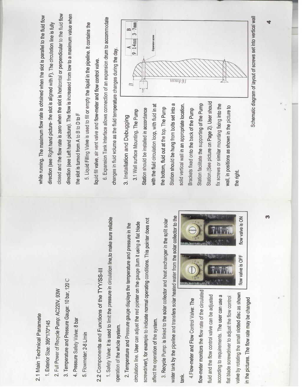
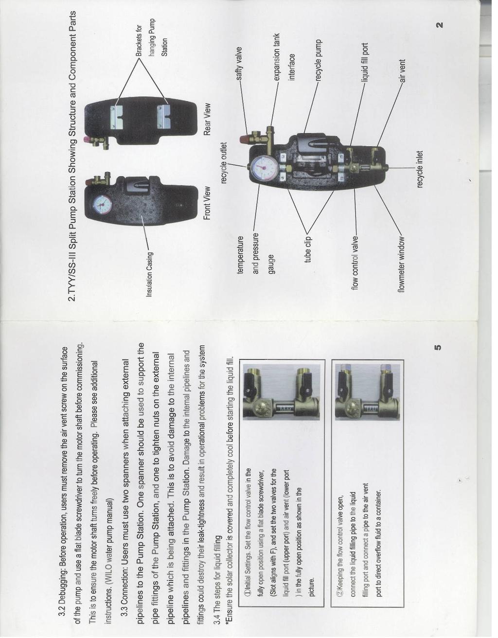
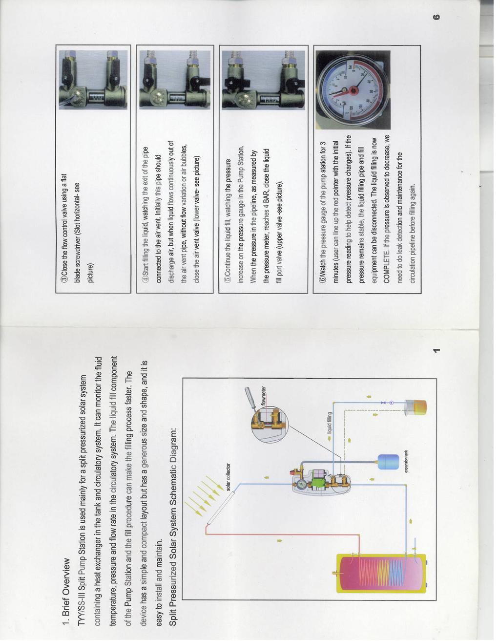
2 Welcome to the SUNRAIN Vaccum Tube Solar Collector! Vacuum tube solar collectors are amongst the most efficient and most costly types of solar collectors. These collectors are best suited for moderate temperature applications where the demand temperature is 50-95C. Vacuum tube solar collectors have a selective absorber for collecting sunlight that is in vacuum-sealed tube, so the thermal losses are very low even in cold climates. Applications of vacuum tube collectors include heating of domestic and commercial hot water, buildings, and indoor swimming pools. Due to their ability to deliver high temperatures efficiently another potential application is for the cooling of buildings by regenerating refrigeration cycles. Our solar collector has been manufactured to the very highest standards, and will provide you with many years of service, with the minimum of maintenance required. This brochure explains how it works, and provides information of a solar water heating installation. Before assembly and installation, please read this brochure carefully.
3 CONTENTS 1. STRUCTURE 2. COMPONENTS 3. TECHNICAL DATA 4. PACKING DETAIL 5. MOUNTING ROOF BRACKET SYSTEM 6. COLLECTOR DIMENSION 7. WARRANTY 8. COLLECTOR IN SYSTEM 9. PROJECT SUGGESTION 10. CONTACT INFORMATION

4 1. STRUCTURE TZ58/ R TZ58/ R WITH STAND TZ58/ R TZ58/ R WITH STAND R1 series R2 series


5 2. COMPONENTS VACUUM TUBE 58/1800mm, selective absorber AL/N-AL


")
")
6 HEAT PIPE, SILICON COTTON STOPPLE AND ALUMINUM FIN dia. 24mm, length 9mm, copper MANIFOLD Aluminum 1 INSULATION CFC Polyurethane foam & Rock Wool TAIL STOCK ABS Plastic (UV stabilized) FRAME STAND (OPTIONAL) Aluminum or Stainless steel 304, 30 or 45
7 3. TECHNICAL DATA TZ R TZ R TZ R TZ R TZ R Total area m m m m m2 Collector m m m m m depth Aperture m m m m m2 area Absorber m m m m m2 area Weight 39.6 kg 54.8 kg 73 kg 91.5 kg 106 kg empty Volume of the fluid 0,7 l (MS) 1,065 l (MS) 1,4 l (MS) 1.85 l (MS) 2,3 l (MS) Efficiency Curve The calculated parameters are based on following areas: aperture area of m absorber area of m : η 0a = η 0A = a 1a = W/m 2 K a 1A = W/m 2 K a 2a = W/m 2 K 2 a 2A = W/m 2 K 2
8 4. PACKING DETAIL TZ58/ , 25, 30R with flat roof stand (For example 25R) NAME All-Glass Evacuated Solar Collector Tube (with heat pipe) Solar Collector with heat pipe (with stand) Solar Collector Frame (with stand) DESCRIPTION 15 PCS/CTN 1 SET/CTN 1 Manifold header, 25 tail stocks, 1 tail stock track, 3 back support bars, 3 joints 1 SET/CTN 3 front tracks, 3 rear tracks, 3 up bars, 3 bottom assistant bars, 4 cross bars TZ58/ , 25, 30R without flat roof stand (For example 25R) NAME All-Glass Evacuated Solar Collector Tube (with heat pipe) DESCRIPTION 15 PCS/CTN Solar Collector with heat pipe 1 SET/CTN 1 Manifold header, 25 tail stocks, 1 tail stock track, 3 back support bars, 3 joints TZ58/ , 15R with flat roof stand (For example 15R) NAME All-Glass Evacuated Solar Collector Tube (with heat pipe) DESCRIPTION 15 PCS/CTN Solar Collector with heat pipe (with stand) Solar Collector Frame (with stand) 1 SET/CTN 1 Manifold header, 15 tail stocks, 1 tail stock track, 3 back support bars, 2 joints 1 SET/CTN 2 front tracks, 2 rear tracks, 2 up bars, 2 bottom assistant bars, 2 cross bars
9 TZ58/ , 15R without flat roof stand (For example 15R) NAME All-Glass Evacuated Solar Collector Tube (with heat pipe) Solar Collector with heat pipe DESCRIPTION 15 PCS/CTN 1 SET/CTN 1 Manifold header, 15 tail stocks, 1 tail stock track, 3 back support bars, 2 joints

10 5. MOUNTING ROOF BRACKET INSTALLATION

11 6. COLLECTOR DIMENSIONS 10R 15R 20R 25R 30R 2010*854*189 mm 2010*1275*189 mm 2010*1680*189 mm 2010*2050*189 mm 2010*2420*189 mm

12 7. COLLECTOR IN SYSTEM
13 8. PROJECT SUGGESTION Pressure Drop Sample Project

14 Swimming pool
15 9. WARRANTY No liability is accepted for incorrect use, unauthorized changes to the assembly components, or the resulting con-sequences. The warranty for the collector lasts for 3years and 1 years for the accessories. All information and instructions in this manual refer to the current state of development. Please always use the respective assembly instructions supplied with the collectors. Figures and illustrations used. Due to the possibility of setting and printing errors, and to the need for continuous technical change, please understand that we cannot accept liability for the correctness of the data. The current version of the General Terms of Business applies. All photographs used are for illustrative purposes only. These assembly instructions contain proprietary information protected by copyright laws. All rights and changes to these assembly instructions are reserved.
16 10. CONTACT INFORMATION JIANGSU SUNRAIN SOLAR ENERGY CO., LTD. Ninghai Industry Zone, Lianyungang, China Contact: Eddy Cheng Tel: , Fax: Web:

 K.")

17 Appendix G Test Report: KTB Nr en Collector test according to EN ,2:2006 for: Jiangsu sunrain solar energy co. ltd, P.R. China Brand name: TZ Responsible for testing: Dipl.-Ing. (FH) K. Kramer Date: 23rd March 2007 Address: Fraunhofer-Institute for Solar Energy Systems ISE Heidenhofstraße 2, D Freiburg Tel.: ; Fax.: korbinian.kramer@ise.fraunhofer.de Internet: Accredited according to DIN EN ISO/IEC 17025:2005 Registration No.: DAP-PL
18 Contents 1 Summary Preliminary remark Collector efficiency parameters determined Incidence angle modifier - IAM Effective thermal capacity of the collector Schedule of tests and callculations Summary statement Test Center 6 3 Orderer, Expeller, Manufacturer 6 4 Overview of series TZ collectors Specific data of the largest collector of the series (TZ R ) Specific data of the smallest collector of the series (TZ R ) Specification of the tubes Absorber Insulation and Casing Limitations Kind of mounting Picture and cut drawing of the collector Collector efficiency parameters Test method Description of the calculation Efficiency parameters Power output per collector unit Incidence angle modifier IAM 16 7 Effective thermal capacity of the collector 17 8 Internal pressure test 17 9 High temperature resistance test 17 KTB Nr en : Collector test according to EN ,2:2006 Jiangsu sunrain solar energy co. ltd, TZ rd March 2007, Fraunhofer-ISE, Heidenhofstraße 2, D Freiburg Page 2 of 30
19 10 Exposure test External thermal shock tests Internal thermal shock tests Rain penetration test Freeze resistance test Mechanical load test Positive pressure test of the collector cover Negative pressure test of fixings between the cover and the collector box Negative pressure test of mountings Stagnation temperature Final inspection Collector identification Summary statement Annotation to the test report 22 A Drawing of absorber layout 23 B Efficiency curve 24 B.1 Efficiency curve with measurement points based on aperture area m B.2 Efficiency curve for the determined coefficients and for an assumed irradiation of 800 W/m 2 based on aperture area B.3 Measured data for efficiency curve C Data of the exposure test 27 KTB Nr en : Collector test according to EN ,2:2006 Jiangsu sunrain solar energy co. ltd, TZ rd March 2007, Fraunhofer-ISE, Heidenhofstraße 2, D Freiburg Page 3 of 30
20 1 Summary 1.1 Preliminary remark The tests have been performed according to EN ,2:2006. Main purpose for testing has been, to fulfill all requirements of the SolarKeymark Scheme rules (version 8.0, January 2003). All requirements have been met. The certificate of the collector minimum gain of 525 kwh/m 2 a is handed. The present report is valid for the series TZ including the collectors TZ 58/ R, TZ 58/ R, TZ 58/ R, TZ 58/ R, TZ 58/ R, TZ 58/ R, TZ 58/ R, TZ 58/ R, TZ 58/ R, TZ 58/ R and TZ R of the company Jiangsu sunrain solar energy co. ltd. The tests were performed at the largest and at the smallest collector of the series. 1.2 Collector efficiency parameters determined Results: The calculated parameters are based on following areas of the collector TZ R. These parameters are valid for the complete series. aperture area of m 2 : absorber area of m 2 : η 0a = η 0A = a 1a = W/m 2 K a 1A = W/m 2 K a 2a = W/m 2 K 2 a 2A = W/m 2 K Incidence angle modifier - IAM θ: K θt : K θl : Table 1: Measured (bold) and calculated IAM data for TZ R 1.4 Effective thermal capacity of the collector Effective thermal capacity (TZ R ): 14.6 kj/k The effective thermal capacity per square meter is (valid for the series): 15.6 kj/k m 2 KTB Nr en : Collector test according to EN ,2:2006 Jiangsu sunrain solar energy co. ltd, TZ rd March 2007, Fraunhofer-ISE, Heidenhofstraße 2, D Freiburg Page 4 of 30
21 1.5 Schedule of tests and callculations Test Date Result Date of delivery: October 26th st internal pressure November 9th 2006 passed High temperature resistance March 3rd 2006 passed Exposure October 26th th March 2007 passed 1st external thermal shock November 15th 2006 passed 2nd external thermal shock March 8th 2006 passed 1st internal thermal shock November 7th 2006 passed 2nd internal thermal shock February 15th 2007 passed Rain penetration November 15th 2006 passed Freeze resistance Mechanical load Stagnation temperature Final inspection not relevant passed C passed Determination of 13th March collector parameters 15th March 2006 passed Determination of IAM Effective thermal capacity passed performed 1.6 Summary statement No problems or distinctive observations occured during the measurements. KTB Nr en : Collector test according to EN ,2:2006 Jiangsu sunrain solar energy co. ltd, TZ rd March 2007, Fraunhofer-ISE, Heidenhofstraße 2, D Freiburg Page 5 of 30
22 2 Test Center Test Center for Thermal Solar Systems of Fraunhofer ISE Heidenhofstraße 2, D Freiburg Tel.: or -5141; Fax.: Internet: 3 Orderer, Expeller, Manufacturer Orderer: Expeller and Manufacturer: Jiangsu sunrain solar energy co. ltd Mr. Jiao Qingtai Ning hai industrial Zone Lianyungang P.R. China Tel: Fax: see orderer KTB Nr en : Collector test according to EN ,2:2006 Jiangsu sunrain solar energy co. ltd, TZ rd March 2007, Fraunhofer-ISE, Heidenhofstraße 2, D Freiburg Page 6 of 30
23 4 Overview of series TZ collectors According to the SolarKeymark Scheme rules (version 8.0, January 2003) there is an agreement concerning collectors, wich differ only in size, so called series or families. Only the biggest and the smallest collector have to be tested in this case. A complete collector test according to EN ,2 has to be performed at the biggest collector. The efficiency test only is sufficient at the smallest collector. The SolarKeymark label based on this tests is valid for the whole series. (MS) = Manufacturer Specification Brand name test collector number of tubes length of tubes TZ R yes m (MS) TZ 58/ R no 12 (MS) m (MS) TZ 58/ R no 14 (MS) m (MS) TZ 58/ R no 15 (MS) m (MS) TZ 58/ R no 18 (MS) m (MS) TZ 58/ R no 20 (MS) m (MS) TZ 58/ R no 24 (MS) m (MS) TZ 58/ R no 25 (MS) m (MS) TZ 58/ R no 28 (MS) m (MS) TZ R yes m (MS) 4.1 Specific data of the largest collector of the series (TZ R ) Brand name: TZ R Serial no.: Year of production: 2006 Number of test collectors: 1 Collector reference no. (ISE): 2 KT (function tests) Total area: m * m = m 2 Collector depth: m Aperture area: Absorber area: Weight empty: Volume of the fluid: m x m x 30 tubes = m m x m x 30 tubes = m kg 2,3 l (MS) KTB Nr en : Collector test according to EN ,2:2006 Jiangsu sunrain solar energy co. ltd, TZ rd March 2007, Fraunhofer-ISE, Heidenhofstraße 2, D Freiburg Page 7 of 30
24 4.2 Specific data of the smallest collector of the series (TZ R ) Brand name: TZ R Serial no.: Year of production: 2006 Number of test collectors: 1 Collector reference no.(ise): 2 KT Total area: m * m = m 2 Collector depth: m Aperture area: Absorber area: Weight empty: Volume of the fluid: 4.3 Specification of the tubes m x m x 10 tubes = m m x m x 10 tubes = m kg 0,7 l (MS) Type: Material of the cover tube: Transmission of the cover tube: Outer diameter of the cover tube: Thickness of the cover tube: Outer diameter of the inner tube Thickness of the inner tube: Distance from tube to tube: (MS) = Manufacturer Specification vacuum tube collector heat pipe, dry conection without mirror borosilicate glass (MS) 91 % (MS) m (MS) m (MS) m (MS) m (MS) m (MS) KTB Nr en : Collector test according to EN ,2:2006 Jiangsu sunrain solar energy co. ltd, TZ rd March 2007, Fraunhofer-ISE, Heidenhofstraße 2, D Freiburg Page 8 of 30
25 4.4 Absorber 4.5 Insulation and Casing Material of the absorber: Cu/Al/SS/N 2 on borosilicate glass (MS) Kind/Brand of selective coating: ALN/SS-ALN/Cu (MS) Absorptivity coefficient α: 94 % (MS) Emissivity coefficient ε: 7 % (MS) Material of the absorber pipes: Layout of the absorber pipes: Outer diameter: Inner diameter: Material of the header pipe: Outer diameter of the header pipe: Inner diameter of the header pipe: Material of the contact sheets: Thickness of the contact sheets: copper (MS) heat pipe, dry conection (MS) m (MS) m (MS) copper (MS) m (MS) m (MS) aluminium (MS) m (MS) Medium between the inner and outer tubes of the vacuum flask: Thickness of the insulation in the header: Material: Material of the casing: Sealing material: high vacuum (MS) m (MS) polyurethane, mineral wool (MS) aluminium (MS) silicon rubber (MS) 4.6 Limitations Maximum fluid pressure: Operating fluid pressure: Maximum service temperature: Maximum stagnation temperature: Maximum wind load: Recommended tilt angle: Flow range recommendation: 1000 kpa (MS) 600 kpa (MS) 95 C (MS) C not spezified (MS) l/m 2 h (MS) KTB Nr en : Collector test according to EN ,2:2006 Jiangsu sunrain solar energy co. ltd, TZ rd March 2007, Fraunhofer-ISE, Heidenhofstraße 2, D Freiburg Page 9 of 30
26 4.7 Kind of mounting Flat roof - mounted on the roof: Tilted roof - mounted on the roof: Tilted roof - integrated: Free mounting: Fassade: yes (MS) no (MS) yes (MS) no (MS) yes (MS) KTB Nr en : Collector test according to EN ,2:2006 Jiangsu sunrain solar energy co. ltd, TZ rd March 2007, Fraunhofer-ISE, Heidenhofstraße 2, D Freiburg Page 10 of 30

27 4.8 Picture and cut drawing of the collector Figure 1: Picture of the collector TZ R facility of Fraunhofer ISE mounted on the test Figure 2: Cut drawing of the collector TZ R KTB Nr en : Collector test according to EN ,2:2006 Jiangsu sunrain solar energy co. ltd, TZ rd March 2007, Fraunhofer-ISE, Heidenhofstraße 2, D Freiburg Page 11 of 30
28 5 Collector efficiency parameters 5.1 Test method Outdoor, steady state according to EN :2006 (tracker) Thermal solar systems and components - solar collectors, Part 2: Test methods 5.2 Description of the calculation The functional dependence of the collector efficiency on the meteorological and system operation values can be represented by the following mathematical equation: η (G,(tm t a) ) = η 0 a 1a t m t a G a (t m t a ) 2 2a G (1) (based on aperture area) t m = te+t in 2 where: G = global irradiance on the collector area (W/m 2 ) t in = collector inlet temperature ( C) t e = collector outlet temperture ( C) t a = ambient temperature ( C) The coefficients η 0, a 1a and a 2a have the following meaning: η 0 : Efficiency without heat losses, which means that the mean collector fluid temperature is equal to the ambient temperature: t m = t a The coefficients a 1a and a 2a describe the heat loss of the collector. The temperature depedency of the collector heat loss is described by: a 1a + a 2a (t m t a ) KTB Nr en : Collector test according to EN ,2:2006 Jiangsu sunrain solar energy co. ltd, TZ rd March 2007, Fraunhofer-ISE, Heidenhofstraße 2, D Freiburg Page 12 of 30
29 5.3 Efficiency parameters Boundary conditions: As the collector is constructed without a reflector or another defined reflecting backside, the effincy messurements were performed by using a tarpaulin with a defined absorption coefficient of 83 %. This corresponds to typical absorption coefficients of common rooftile. Test method: outdoor, steady state Latitude: 48.0 Longitude: 7.8 Collector tilt: tracked between 35 and 55 Collector azimuth: tracked Mean irradiation : 936 W/m 2 Mean wind speed: 3 m/s Mean flow rate: 66 kg/h Kind of fluid: water date of the Measurement February 2007 Results: The calculated parameters are based on following areas of the collector TZ R. These values are also valid for the complete series. 1 : aperture area of m 2 : absorber area of m 2 : η 0a = η 0A = a 1a = W/m 2 K a 1A = W/m 2 K a 2a = W/m 2 K 2 a 2A = W/m 2 K 2 The determination for the standard deviation (k=2) was performed according ENV (GUM). Based on this calculation the uncertainty is less than 2%-points of the efficiency values over the complete measured temperature range ( η 0a = /- 0.02). Based on our experience with the test facilities the uncertainty is much smaller and in a range of +/- 1%-point. The standard deviation of the heat loss parameters resulting from the regression fit curve through the measurement points is: a 1a = / and a 2a = / For more detailed data and the calculated efficiency curve please see annex B. 1 absorber area - projected area of absorber tube, aperture area - projected area of inner diameter of cover tube KTB Nr en : Collector test according to EN ,2:2006 Jiangsu sunrain solar energy co. ltd, TZ rd March 2007, Fraunhofer-ISE, Heidenhofstraße 2, D Freiburg Page 13 of 30
30 5.4 Power output per collector unit The power output per collector unit will be documented for the largest collector of the series TZ R with the highest output per collector unit and for the smallest collector of the series TZ R with the lowest output per collector unit Power output per collector unit [W] t m -t a [K] Figure 3: Power output for collector TZ R based on 1000 W/m 2 Power output per collector unit [W] for collector TZ R (aperture area of m 2 ): t m t a [K] 400 [W/m 2 ] 700 [W/m 2 ] 1000 [W/m 2 ] KTB Nr en : Collector test according to EN ,2:2006 Jiangsu sunrain solar energy co. ltd, TZ rd March 2007, Fraunhofer-ISE, Heidenhofstraße 2, D Freiburg Page 14 of 30
31 Power output per collector unit [W] t m -t a [K] Figure 4: Power output for collector TZ R based on 1000 W/m 2 Power output per collector unit [W] for collector TZ R (aperture area of m 2 ): t m t a [K] 400 [W/m 2 ] 700 [W/m 2 ] 1000 [W/m 2 ] The power output per collector unit can be calculated for other collectors of this series according to the follwoing procedure: with: P = P ref Aa A a,ref P = Collector output for a different collector of the series P ref = Collector output for collector TZ R, (values see table) A a = Aperture area of a different collector of the series A a,ref = Aperture area of collector TZ R = m 2 KTB Nr en : Collector test according to EN ,2:2006 Jiangsu sunrain solar energy co. ltd, TZ rd March 2007, Fraunhofer-ISE, Heidenhofstraße 2, D Freiburg Page 15 of 30
32 6 Incidence angle modifier IAM The IAM (= Incidence Angle Modifier) is a correction factor representing how the angle of incident radiation affects the performance of a collector. For collectors which have a direction-depending IAM behaviour (for example vacuum tube collectors and collectors with CPC reflectors), it is necessary to meassure the IAM for more than one direction, to have a proper determination of the IAM. The complex IAM can be estimated by calculating it as the product of both separately meassured incidence angle modifiers K θl and K θt of two orthogonal planes (equation 2). K θ = K θl xk θt (2) The longitudinal plane (index L) is orientated parallelly to the optical axsis of the collector. The transversal plane is orientated orthogonally to the optical axsis of the collector. The angles θt and θl are the projection of the incidance angle of the radiation on the transversal or longitudinal plane. Test method: Latitude: Longitude: Collector tilt: Collector azimuth: outdoor, steady state tracked tracked θ: K θt : K θl : Table 2: Measured (bold) and calculated IAM data for TZ R The angles for the transversal IAM in table 2 were calculated according to Ambrosetti 1 (equation 3). K θ = 1 [tan θ 2 ] 1 r (3) 1 P.Ambrosetti. Das neue Bruttowärmeertragsmodell für verglaste Sonnenkollektoren, Teil 1 Grundlagen. EIR, Wurenlingen 1983 KTB Nr en : Collector test according to EN ,2:2006 Jiangsu sunrain solar energy co. ltd, TZ rd March 2007, Fraunhofer-ISE, Heidenhofstraße 2, D Freiburg Page 16 of 30
33 7 Effective thermal capacity of the collector The effective thermal capacity of the collector is calculated according to section of EN :2006. For the heat transfer fluid a mixture 2/1 of water/propylenglycol at a temperature of 50 C has been chosen. Effective thermal capacity (TZ R ): 14.6 kj/k The effective thermal capacity per square meter is (valid for the series): 15.6 kj/k m 2 8 Internal pressure test Maximum pressure: Test temperature: Test pressure: Test duration: 1000 kpa (MS) 12.3 C 1500 kpa (1.5 times the maximum pressure) 15 min Result: During and after the test no leakage, swelling or distortion was observed or measured. 9 High temperature resistance test Method: Indoor testing Collector tilt angle: 45 Average irradiance during test: 1011 W/m 2 Average surrounding air temperature: 25.3 C Average surrounding air speed: < 0.5 m/s Average absorber temperature: 197,5 C Duration of test: 1 h Result: No degradation, distortion, shrinkage or outgassing was observed or measured at the collector. KTB Nr en : Collector test according to EN ,2:2006 Jiangsu sunrain solar energy co. ltd, TZ rd March 2007, Fraunhofer-ISE, Heidenhofstraße 2, D Freiburg Page 17 of 30
34 10 Exposure test The collector tilt angle was 45 facing south. Annex C shows all test days of the exposure test. Result: The number of days when the daily global irradiance was more than 14 MJ/m 2 d was 41. The periods when the global irradiance G was higher than 850 W/m 2 and the surrounding air temperature t a was higher than 10 C was 41.7 h. The evaluation of the exposure test is described in the chapter 17 "Final inspection". 11 External thermal shock tests Test conditions 1st test 2nd test Outdoors: yes yes Combined with exposure test: yes yes Combined with high temperatur resistance test: no no Collector tilt angle: Average irradiance: 850 W/m W/m 2 Average surrounding air temperature: 17.8 C 12.6 C Period during which the required operating conditions were maintained prior to external thermal shock: 1 h 1 h Flowrate of water spray: 0.05 l/m 2 s 0.05 l/m 2 s Temperature of water spray: 16.6 C 16.0 C Duration of water spray: 15 min 15 min Absorber temperature immediately prior to water spray: C C Result: No cracking, distortion, condensation or water penetration was observed or measured at the collector. KTB Nr en : Collector test according to EN ,2:2006 Jiangsu sunrain solar energy co. ltd, TZ rd March 2007, Fraunhofer-ISE, Heidenhofstraße 2, D Freiburg Page 18 of 30
35 12 Internal thermal shock tests Test conditions 1st test 2nd test Outdoors: yes yes Combined with exposure test: yes yes Combined with high temperature resistance test: no no Collector tilt angle: Average irradiance: 884 W/m W/m 2 Average surrounding air temperature: 9.8 C 10.4 C Period during which the required operating conditions were maintained prior to internal thermal shock: 1 h 1 h Flowrate of heat transfer fluid: 0.02 l/m 2 s 0.02 l/m 2 s Temperature of heat transfer fluid: 16.6 C 16.4 C Duration of heat transfer fluid flow: 5 min 5 min Absorber temperature immediately prior to heat transfer fluid flow: C C No cracking, distortion or condensation was observed or measured at the collector. 13 Rain penetration test Collector mounted on: Method to keep the absorber warm: Flowrate of water spray: Duration of water spray: Open frame Exposure of collector to solar radiation 0.05 l/m 2 s 4 h Result: No water penetration was observed or measured at the collector. 14 Freeze resistance test The freeze resistance test is not relevant, because the manufacturer suggestst a application of the collector only with a freeze resistance fluid. 15 Mechanical load test 15.1 Positive pressure test of the collector cover This test was not performed by means of implementing pressure. The collector was visualy observed and the structur was checked from a technical point of view. KTB Nr en : Collector test according to EN ,2:2006 Jiangsu sunrain solar energy co. ltd, TZ rd March 2007, Fraunhofer-ISE, Heidenhofstraße 2, D Freiburg Page 19 of 30
36 15.2 Negative pressure test of fixings between the cover and the collector box This test was not performed by means of implementing pressure. The collector was visualy observed and the structur was checked from a technical point of view Negative pressure test of mountings The mechanical load test is not reasonable for this collector because of the vacuum tube type without reflector. 16 Stagnation temperature The stagnation temperature was measured outdoors. The measured data are shown in the table below. To determine the stagnation temperature, these data were extrapolated to an irradiance of 1000 W/m 2 and an ambient temperatur of 30 C. The calculation is as follows: t s = t as + G s G m (t sm t am ) (4) t s : Stagnation temperature t as : 30 C G s : 1000 W/m 2 G m : Solar irradiance on collector plane t sm : Absorber temperature t am : Surrounding air temperature Irradiance Surrounding air Absorber temperature temperature [W/m 2 ] [ C] [ C] The resulting stagnation temperature is: C KTB Nr en : Collector test according to EN ,2:2006 Jiangsu sunrain solar energy co. ltd, TZ rd March 2007, Fraunhofer-ISE, Heidenhofstraße 2, D Freiburg Page 20 of 30
37 17 Final inspection The following table shows an overview of the result of the final inspection. Collector component Potential problem Evaluation Collector box/ fasteners Cracking/ wraping/ corrosion/ 0 rain penetration Mountings/ structure Strength/ safety 0 Seals/ gaskets Cracking/ adhesion/ elasticity 0 Cover/ reflector Cracking/ crazing/ buckling/ delamination/ 0 wraping/ outgassing Absorber coating Cracking/ crazing/ blistering 0 Absorber tubes and headers Deformation/ corrosion/ leakage/ 0 loss of bonding Absorber mountings Deformation/ corrosion 0 Insulation Water retention/ outgassing/ 0 degradation 0: No problem 1: Minor problem 2: Severe problem x: Inspection to establish the condition was not possible 18 Collector identification The collector identification/documentation according EN chapter 7 was complete, see the following items: Drawings and data sheet Labeling of the collector Installer instruction manual (not for mounting integrated in tilted roof or fassade mounting, no pressure lost) List of used materials KTB Nr en : Collector test according to EN ,2:2006 Jiangsu sunrain solar energy co. ltd, TZ rd March 2007, Fraunhofer-ISE, Heidenhofstraße 2, D Freiburg Page 21 of 30
38 19 Summary statement The measurements were carried out from October 2006 until February No problems or distinctive observations occured during the measurements. 20 Annotation to the test report The results described in this test report refer only to the test collector. It is not allowed to make extract copies of this test report. Test report: KTB Nr en Freiburg, 23rd March 2007 Fraunhofer-Institute for Solar Energy Systems ISE Dipl.-Phys. M. Rommel Head of the Test Center for Thermal Solar Systems Dipl.-Ing. (FH) K. Kramer Responsible for testing and report KTB Nr en : Collector test according to EN ,2:2006 Jiangsu sunrain solar energy co. ltd, TZ rd March 2007, Fraunhofer-ISE, Heidenhofstraße 2, D Freiburg Page 22 of 30
39 A Drawing of absorber layout Figure 5: Drawing of absorber layout TZ R KTB Nr en : Collector test according to EN ,2:2006 Jiangsu sunrain solar energy co. ltd, TZ rd March 2007, Fraunhofer-ISE, Heidenhofstraße 2, D Freiburg Page 23 of 30
40 B Efficiency curve B.1 Efficiency curve with measurement points based on aperture area m Efficiency η (based on aperture area) Δt/G [K*m 2 /W] Figure 6: Efficiency curve with measurement points based on aperture area m 2 Results: The calculated parameters are based on following areas: aperture area of m 2 : absorber area of m 2 : η 0a = η 0A = a 1a = W/m 2 K a 1A = W/m 2 K a 2a = W/m 2 K 2 a 2A = W/m 2 K 2 KTB Nr en : Collector test according to EN ,2:2006 Jiangsu sunrain solar energy co. ltd, TZ rd March 2007, Fraunhofer-ISE, Heidenhofstraße 2, D Freiburg Page 24 of 30
41 B.2 Efficiency curve for the determined coefficients and for an assumed irradiation of 800 W/m 2 based on aperture area Efficiency η (based on aperture area) Δt/G [K*m 2 /W] Figure 7: Efficiency curve scaled to 800 W/m 2 based on aperture area m 2 The calculated parameters are based on following areas: aperture area: absorber area: η 0.05a = η 0.05A = η 0.05 is the efficiency of the collector for typical conditions of solar domestic hot water systems: irradiation of 800 W/m 2, ambient temperature of 20 C mean collector temperture of 60 C. KTB Nr en : Collector test according to EN ,2:2006 Jiangsu sunrain solar energy co. ltd, TZ rd March 2007, Fraunhofer-ISE, Heidenhofstraße 2, D Freiburg Page 25 of 30
42 B.3 Measured data for efficiency curve G G d /G m t in t e t e t in t m t a t m t a (t m t a )/G η a [W/m 2 ] [-] [kg/h] [ C] [ C] [K] [ C] [ C] [K] [K m 2 /W] [-] Table 3: Data of measured efficiency points KTB Nr en : Collector test according to EN ,2:2006 Jiangsu sunrain solar energy co. ltd, TZ rd March 2007, Fraunhofer-ISE, Heidenhofstraße 2, D Freiburg Page 26 of 30
43 C Data of the exposure test H: daily global irradiation valid period: periods when the global irradiance G is higher than 850 W/m 2 t a : rain: and the surrounding air temperature t a is higher than 10 C surrounding air temperature daily rain [mm] Date H valid period t a rain [MJ/m 2 ] [h] [ C] [mm] KTB Nr en : Collector test according to EN ,2:2006 Jiangsu sunrain solar energy co. ltd, TZ rd March 2007, Fraunhofer-ISE, Heidenhofstraße 2, D Freiburg Page 27 of 30
44 Continuation, see next page: Continuation, see next page: Date H valid period t a rain [MJ/m 2 ] [h] [ C] [mm] not spezified not spezified not spezified not spezified not spezified not spezified not spezified not spezified not spezified not spezified not spezified not spezified not spezified not spezified not spezified not spezified not spezified not spezified not spezified not spezified not spezified not spezified not spezified not spezified KTB Nr en : Collector test according to EN ,2:2006 Jiangsu sunrain solar energy co. ltd, TZ rd March 2007, Fraunhofer-ISE, Heidenhofstraße 2, D Freiburg Page 28 of 30
45 Continuation, see next page: Date H valid period t a rain [MJ/m 2 ] [h] [ C] [mm] not spezified not spezified not spezified not spezified not spezified not spezified not spezified not spezified not spezified not spezified not spezified not spezified not spezified not spezified not spezified not spezified not spezified not spezified not spezified not spezified not spezified KTB Nr en : Collector test according to EN ,2:2006 Jiangsu sunrain solar energy co. ltd, TZ rd March 2007, Fraunhofer-ISE, Heidenhofstraße 2, D Freiburg Page 29 of 30
46 Date H valid period t a rain [MJ/m 2 ] [h] [ C] [mm] KTB Nr en : Collector test according to EN ,2:2006 Jiangsu sunrain solar energy co. ltd, TZ rd March 2007, Fraunhofer-ISE, Heidenhofstraße 2, D Freiburg Page 30 of 30

47 Appendix H
48 TABLE OF CONTENTS A/C DESCRIPTION Components A/C Features Cooling/heating Principle Circuit Diagram Dimensions INSTALLATION Installation Requirement Air Distribution Water Circulation OPERATION Control Panel Instruction Remote Control Instructions GENERAL TROUBLESHOOTING MAINTENANCE MANUFACTURERS LIMITED WARRANTY AGREEMENT
49 A/C DESCRIPTION Components MSBA6 Coaxial Exchanger Tube Refrigerant Tube Holding Ring Air Outlet Drain Connection Charging Port Conduit Connector Drain Connection Rotatable Blower Water Outlet Filter Water Inlet Drain Connection Temperature and Humidity Sensor Drain Connection 1
50 A/C DESCRIPTION Components MSBA9 Coaxial Exchanger Tube Holding Ring Conduit Connector Water Outlet Refrigerant Tube Water Inlet Drain connection Rotatable Blower Drain Connection Air Outlet Drain Connection Filter Charging port Drain Connection Temperature and Humidity Sensor Drain connection 2
51 A/C DESCRIPTION Components MSBA11 MSBA14 MSBA16 Coaxial Exchanger Tube Holding Ring Conduit Connector Refrigerant Tube Drain Connection Rotatable Blower Drain Connection Air Outlet Drain Connection High Pressure Gauge Low Pressure Gauge Water Outlet Filter Water Inlet Drain Connection Charging port Temperature and Humidity Sensor Drain Connection 3
52 A/C DESCRIPTION A/C Features MSBA9,MSBA11,MSBA14,MSBA Degree Rotatable Blower Fan 360 Degree Rotatable Blower. The unique design makes it very easy to rotate the blower outlet. The blower can be rotated in any angle within minutes. MSBA6 can be rotated only up to 90 angle. (To change air direction, just loosen the metal clamp, then adjust it to the desired angle and re-tighten the metal clamp) High, low pressure gauge and charging port Low pressure gauge (Blue) High pressure gauge (Red) Charging Port Entering Water Temperature Low Pressure at Cooling operation High Pressure at Cooling operation Low Pressure at ing operation High Pressure at ing operation No No oper ation oper ation No No oper ation oper ation No oper ation No oper ation No oper ation No oper ation No oper ation No oper ation F PSI PSI PSI PSI 4
53 A/C DESCRIPTION Principles of Refrigeration and ing Cooling mode Evaporator High pressure Four way valve Capillary tube (cooling) Fan High pressure Inlet Outlet Water outlet Liquid Water inlet exchanger Compressor ing mode Evaporator High pressure Liquid Four way valve Capillary tube (heating) Fan Inlet Outlet Water outlet Water inlet exchanger Compressor 5
54 WIRING DIAGRAM L N PL PN WIRING DIAGRAM C2 FM 1 ~ FAN MOTOR COMPRESSOR C1 CM 1 ~ 12V Transformer L1 L2 AC220V/50Hz AC230V/60Hz 2 Ground Ground 1 P.C.B L N PL PN Some models may have single speed motor please refer to the wiring diagram in the electric box. 6
55 DIMENSIONS Dimensions MSBA6K2 Dimensions (in/mm) 17.5/ /242 10/251 11/280 4/101 7
56 DIMENSIONS Dimensions MSBA6C2 Dimensions (in/mm) 17.5/ /242 11/280 11/280 4/101 8
57 DIMENSIONS Dimensions MSBA9 Dimensions (in/mm) 22.7/ / / /374 6/152 9
58 DIMENSIONS Dimensions MSBA11,MSBA14,MSBA16 Dimensions ( in/mm ) 23.2/ / / / /50 1.4/35 G 6/152 G 10
59 INSTALLATION Clean Air Act MarinAire MSBA series use environmentally friendly refrigerant R410A. Refer to for rules & regulations on how to handle R410A. Operation Limits Cooling Operation: Incoming Water temperature (sea, river, lake water temperature) of 60 F to 95 F ing Operation: Incoming Water temperature (sea, river, lake water temperature) of 40 F to 77 F Caution: Operating your air conditioner & heat pump out of above mention ranges might cause permanent damage to the compressor, heat exchangers, pump, and other plumbing components.! The location of the ac must be sealed from bilge and/or engine room vapors. Do not install your air conditioner in the bilge or engine room areas.. Condensate drain hose should not be terminated closed to any outlet of engine, generator exhaust systems, in a bilge. Air conditioner or electric box must not be placed in an explosive environment or exposed to an explosive environment or explosive materials, explosion could occur resulting in serious injury or death and/or destruction of the boat. This equipment does not meet requirements for ignition protection. Do not install in spaces containing gasoline engines, lpg/cpg cylinders, tanks, valves, regulators or fuel line fittings. Failure to comply may result in damages, serious injury or death. Drain line should be connected properly to a sealed condensate tank or shower sump pump. Installation and servicing of this system can be hazardous. Similar to other air conditioning systems, this equipment involves electrical and high pressure components. Always disconnect power supply prior to perform installation, servicing or maintenance. To minimize the hazard of electrical shock and personal injury, this equipment must be grounded. All Instructions labels and safety codes must be followed when working with this unit. When running, the compressor, and heat exchangers may be hot. Do not touch the equipment when running. Sizing Warning Make sure the selected capacity is not oversized for the applicable are. Over sizing might cause damage to the electrical components and/or to the power supply due to frequent start and stop. Over sized air conditioning will not effectively remove the humidity and this may cause high humidity and mold in the cabin. This may also cause high energy consumption. Slightly under sizing may be applicable but significantly under sizing your air conditioning will cause discomfort when you need it the most! The general rule of thumb for sizing a pleasure boat is 14BTU's/cubic foot Use the formula of 16 to 19 BTU's/cubic foot for areas that are used during the heat of the day that have a lot of sunlight coming in such as a pilothouse, especially if the roof is not shaded or well insulated. For areas below deck that are primarily used after sunset such as a stateroom, you can use the formula of BTU's/cubic foot Location of the system Typical spots are under the V-berth, in hanging lockers, under dinette seats, in cabinets or in outside dry lazarets and bottom of lockers. The equipment and peripheral components must fit in and/or be accessible to the selected spot. The unit should be positioned on a firm, level, horizontal (flat) surface and the condensate drain line should run down slope from the unit to a suitable drain location. Drain works with gravity. If you can not find a location for the size of the air conditioner base plate, a mounting shelf or platform must be built. Typically the shelf may be made from 3/4 inch marine grade plywood which can be either fiber glassed or mechanically attached to the boat's sole or superstructure. Do not screw directly into the hull. Never place the electrical box below the air conditioning unit. It is strongly recommended that you locate the return grille as low as possible and the supply air grilles as high as possible in the cabin. This will provide better air circulation. You should plan all connections including ducting, splitter, grilles, condensate drain, water in and out, water filter, water circulation pump, electrical power connections and location of the wall control unit, 11
60 INSTALLATION Mounting legs & Vibration Absorbers The a/c unit is supplied with a base pan that also serves as a condensate pan. Mounting legs and vibration absorbers are provided to secure the base pan onto a flat surface. AIR DISTRIBUTION Blower Assembly The ultimate engineering design allows the blower to be easily rotated 360 for best angle or removed for servicing. Simply loosen the metal clamp and rotate the blower outlet to the desired angle and tight the metal clamp again. Do not leave the clamp loose and do not over tight it since it may apply tension to the shroud and may cause crack. Ducting Install at least one vent within 4 to 5 feet of the unit. Make sure that the airflow is not directed back towards the return air grill. Below rule should be followed as a rule of thumb; 6,000 btu unit: 2 or 3 X 4 supply grills. 9,000-11,000 btu unit: 3 or 4 X 4 supply grills 14,000 btu unit: 3 or more X 4 supply grills or 1 X 6 supply grill and 2 or more X 4 supply grills 16,000 btu unit: 1 X 6 supply grill and 2 or more X 4 supply grills 24,000 btu unit: 3 or more X 6 supply grills An air splitter is required if more than one supply air grill is used. Splitters may be mounted directly on the unit output, or placed in line a short distance from the unit incase of space restrictions. Use insulated duct if the ducting passes through hot and humid areas. If the ducting is completely inside the air conditioned area, you may use non-insulated duct. Using non insulated duct may cause water condensation. Usually power boats use non-insulated duct and sail boats insulated. Sail boats generally sit lower in the water and have less glass than power boats, they tend to produce more duct condensation than the power boat. All duct runs should be as short and straight as possible. Each 90 bends can reduce airflow by 15% to 20%. Ducting should be tied to a permanent structure properly to eliminate sagging. Four inch round grills require a 4.5 inch hole. A four inch rectangular grill usually measures 4x8 for the hole size but also requires a booth or transition box behind the grill, also measuring 4x8.These booths extend approximately four inches behind the wall. Booths (transition box) are needed to attach the air duct to the grill. Return Air 5000 btuh to 9000btuh needs square inches (8X10 to 10X10 ) btuh to 24000btuh needs square inches (10X12 to 10X15 ) Always use return grilles with filter. Make sure that the air returns to the a/c unit is properly filtered. Insure that there is no air passing to the return of the unit from elsewhere. Unfiltered air with dust, dirt and debris will cause poor performance and potentially malfunction. Do not put any object to obstruct the return air grill. For best performance the evaporator side of the unit should face the return air grill. The evaporator should be at least 3 away from the wall if installed sideways. Where it is not possible to have a single return grill multiple grills may be used. Do not stow items such as life preservers, bedding or other items of this nature between the evaporator and the return air grill. 12
61 INSTALLATION WATER CIRCULATION Condensate Drain Connection During cooling or dehumidifying mode operations, the air conditioner may produce approximately 1/2 gallon per hour. It is important to run condensate drains hose downward to a sump pump. Do not run the condensate drains to the bilge. After the condensate drain connection is complete, test the installation by pouring? gallon of water within 1 minute into the drain pan and checking for good flow. Water in & out Cooling water is provided to the air conditioner via a foot scoop, sea cock, water strainer and pump assembly all of which are mounted at least 1 feet below the sea level. Use 5/8 inch marine water hose. Water in is always located at the lower position and Water out is located at higher position. (from the coaxial condenser heat exchanger). Incase water connection is not straight, it is recommended to use a hose barb 90 degree fitting to eliminate any kinking. Insure that the hoses will never be kinked. Install a sea water strainer between the sea cock and the pump. Seawater strainer must be installed below the level of the pump with access to filter. Connect the water out directly to the Thru the hull fitting which is located above the sea level. Double clamp all hose connections with stainless steel clamps, reversing the clamps. Use Teflon tape on all threaded connections. Refer to below illustration for details. Correct Water installations has been increasing steadily, and then drop outlet Incorrect Connecting pipes are bending Outlet Outlet A/C A/C Under water Filter Pump Under water Filter Pump Inlet Ball Valve Inlet Ball Valve Incorrect Filter higher than the water pump Incorrect Pumps and filters have been higher than the water level Outlet Outlet A/C Filter A/C Filter Pump Pump Under water Under water Inlet Ball Valve Inlet Ball Valve 13
62 INSTALLATION Electrical Power: Both the air conditioner and pump require same voltage. Make sure the power source is correct for the equipment. ( V/60Hz, V/60Hz and V/50Hz models available) Power is obtained from the master Circuit Breaker Panel in the boat. Power cables run from this panel to the air conditioner. The air conditioner will then supply power to the pump as required. A terminal strip mounted inside the Electrical box. The terminal strip is labeled for proper connections of the electrical supply, ground wires and pump circuits. A wiring diagram is provided in the electrical box. Minimum of 12 AWG boat cable should be used to supply power to the a/c unit and the seawater pump. Proper grounding is mandatory. A ground connection is provided in the electrical box. All connections shall be made with ring or captive fork terminals. Pump will be connected directly to the terminal strip in the electrical box. Turn off a/c power supply circuit breaker before opening electric box. The a/c unit must be connected to the ship's bonding system to prevent corrosion due to stray electrical current or voltage. All pumps, metallic valves and fittings in the seawater circuit that are isolated from the a/c unit by PVC or rubber hoses must be individually bonded to the vessels bonding system too. OPERATION Control Panel Operation 1. Auto mode 2. Dehumidifying mode 3. Fan mode 4. Cooling mode 5. ing mode 6. Temperature Display 7. Fan speed 8. Humidity Display 9. Timer R MarinAire MODE FAN POWER UP DOWN A>. When LCD display backlight is off, press any button to light up the backlight; the setting values on display will blink 5 times (one per second), then it will go back to display room temperature and humidity. Backlight will be off 10 seconds later. B>. The button on controller: "MODE", "FAN", "POWER", "UP" and "DOWN". C>. "UP" and "DOWN": set the temperature in auto, cooling and heating mode, or humidity level in dehumidifying mode by directly pressing "UP" and "DOWN" button. In cooling, heating and auto mode, press "UP" and "DOWN" to enter temperature setting. The temperature blinks (one per second); In humidity and auto dehumidifying mode, press "UP" and "DOWN" to enter humidity setting. The humidity blinks (one per second). Press "UP" and "DOWN" together o o for 5 seconds to switch temperature unit ( to F or F to ). D>. "MODE": press "MODE" to set operation mode: Auto, Cooling, Dehumidifying, ing, Auto Dehumidifying and Fan. E>. "Fan mode": to set fan motor operation mode. Auto speed, high speed, medium speed, and low speed. F>. "POWER": to turn on/turn off the a/c. G>. Use the remote control to set timer; The timer symbol will be displayed on LCD. 14
63 OPERATION Name and Function 1. Signal Transmitter 2.Temperature and Humidity display 3.Timer ON display 4.Cooling mode symbol 5.ing mode symbol 1. 6.Mode button 7.Timer ON button 8.High speed button 9.Mid speed button 10.Auto speed display 11.High speed display ON OFF HI MED LO Low speed display 13.Mid speed display 14.Timer OFF display 15.Auto Mode symbol 16.Fan Mode symbol Dehumidifying Mode symbol 18.UP/DOWN buttons 6. MODE C/ F Unit change button 20.Timer OFF button 7. TIMER /ON TIMER/OFF Low speed button 22.Power button 8. HIGH MID LOW
64 OPERATION AUTO mode Display If the setting temperature is greater than the room temperature, the unit will automatically switch to heating mode. If the setting temperature is lower than the room temperature, the unit will automatically switch to cooling mode. If the setting temperature is equal to room temp the unit will run on low fan speed. 1 Press the MODE button to select the AUTO mode. MODE C/ F 2 Press the UNIT CHANGE button to set the temperature unit TIM ER/ON TMER/O I FF 3 Press the UP/DOWN button to set the temperature. HIGH MID LOW 16
65 OPERATION Remote Control Operation Cooling mode Display MED Use cooling function only when the sea water temperature is between 60F to 95F. Do not operate the unit under cooling mode when the sea water temperature is out of this range. 1 Press the MODE button to select the cooling mode. MODE C/ F 2 Press the UNIT CHANGE button to set the temperature unit TIM ER/ON TMER/O I FF 3 Press the UP/DOWN button to set the temperature. HIGH MID LOW 4 Press the HIGH/MID/LOW button to set the fan speed. Auto fan function can only be set on LCD wall panel. Once the auto fan is set, the fan will stop after a while when the compressor stops. 17
66 OPERATION Dehumidifying mode Display LO Please note that there is a humidity sensor installed in the system. Therefore desired humidity level can be set between 40% and 85%. Once the setting level is achieved the unit will stop. Fan will run every 10 minutes for 3 minutes to detect the current humidity level. Use dehumidifying mode only when the sea 0 water temperature is between 60 F 0 and 95 F. Do not operate the unit under this mode when the sea water temperature is out of this range. MODE TIM ER/ON C/ F TMER/O I FF 1 Press the MODE button to select the dehumidifier; The fan speed will be automatically locked for low-speed position. HIGH MID LOW 2 Press the UP/DOWN button to set the humidity level. This mode is recommended When the users are on the boat 18
67 OPERATION Fan mode Display HI This mode is used to circulate the air in the cabin there won t be any cooling or heating effect. 1 Press the MODE button to select the fan mode. MODE C/ F TIM ER/ON TMER/O I FF HIGH MID LOW 2 Press the HIGH/MID/LOW button to preset the fan speed. 19
68 OPERATION ing mode Display MED ing function is provided by reverse cycle of the Refrigerant circuit ( Pump). There is no electric heating element installed in this system. Use heating function only when the sea water temperature is between 40F to 77F. Do not operate the unit under heating mode when the sea water temperature is out of this range 1 Press the MODE button to select the heating mode. MODE C/ F 2 Press the UNIT CHANGE button to set the temperature unit TIM ER/ON TMER/O I FF 3 Press the UP/DOWN button to set the temperature. HIGH MID LOW 4 Press the HIGH/MID/LOW button to set the fan speed. Auto fan function can only be set on LCD wall panel. Once the auto fan is set, the fan will stop after a while when the compressor stops. 20
69 OPERATION Timer on Display MED Use Timer On function to start the unit at any time within the next 24 hour. 24 ON 1 Press the TIMER ON button to activate timer on function when the unit is switched off. And Press one time to add one hour. MODE C/ F TIM ER/ON TMER/O I FF HIGH MID LOW 21
70 OPERATION Timer off Display MED Use Timer Off function to turn off the unit at any time within the next 24 hour. 24 OFF 1 Press the TIMER OFF button to activate timer off function when the unit is switched on. And Press one time to add one hour. MODE C/ F TIM ER/ON TMER/O I FF HIGH MID LOW 22
71 OPERATION Auto Dehumidifying mode Display LO Please note that there is a humidity sensor installed in the system. Therefore desired humidity level can be set between 40% and 85%. Once the setting level is achieved the unit will stop. Fan will run every 60 minutes for 3 minutes to detect the current humidity level. Use humidifying mode only when the sea water temperature is between 60 0F and 95 0F. Do not operate the unit under this mode when the sea water temperature is out of this range. MODE TIM ER/ON C/ F TMER/O I FF 1 Press the MODE button to select the dehumidifier; The fan speed will be automatically locked for low-speed position. HIGH MID LOW 2 Press the UP/DOWN button to set the humidity level. This mode is recommended When the users are not on the boat. (Left the boat for one or more days) 23
72 OPERATION Install and Change the Battery 1) Open the cover of remote control, hold the hook and lightly pull up. 2) Insert the batteries, and check if the batteries are placed in the correct position. 3) Reinstall the cover. 24
73 MALFUNCTIONS INSTRUCTION 1 Humidity sensor error When the humidity sensor is short-circuited or open-circuited, the control panel LCD will display E0. In this case, please call for service. 2 Freeze Protection Display will show "E1", When coil tube temperature sensor < 30 F and continuously maintains it for more than one minute. After few minutes, it should reset automatically if the coil temperature gets 46 F or above. Incase the display continuously shows E1, Stop operation, turn off the power and call a technician for diagnosing the problem. 3 Indoor temperature sensor Error Display will show "E2", when Indoor temperature sensor loose or broken, a qualified technician should be called 4 Coil temperature sensor Error Display will show "E3", when coil temperature sensor loose or broken, a qualified electrician should be called 5 High Pressure protection The control panel will display E4 error code when the high pressure switch cuts out. The high pressure switch may cut out temporarily and it may reset again. If there are multiple cut outs,the unit should be turned off and water flow should be inspected. There may be blockage on air flow during heating operation or the water temperature may be too high. 25
74 MALFUNCTIONS INSTRUCTION 6 Low Pressure protection The control panel will display E5 error code when the low pressure switch cuts out.the low pressure switch may cut out temporarily and it may reset again. If there are multiple cut outs, the system may not resume normal operation. A qualified technician should be called. 7 Water Level Protection The controller board is equipped with a function that an optional flow switch may be connected. In case a switch is used and water flow level is low the system will display E7 error code.check the pump s operation. 8 Overheating protection Display will show"e9", when coil tube temperature sensor > 145 F at heating mode. A qualified technician should be called to determine the reason of overheating. 9 Communication Error Display showing EA means that the phone lines are not connected well with the control panel.we recommend to check and replace the cable. 26
75 MAINTENANCE Reversing Valves Pump units bear a reversing valve; the valve must be energized periodically to keep the internal parts moving freely. To do this, switch the a/c unit into heat for a few seconds once a month. Seawater Strainer Clean the strainer periodically to a for a steady stream of water. Check seawater intake scoop for obstructions. Hoses & fittings Make sure there is no leak at the connection points and also make sure that hoses are not looped, kinked or crushed. Flushing the Condenser Coil 1. Turn off at the circuit breaker. Disconnect the inlet and outlet connections of the condenser coil. 2. Use chemical resistant pump and hoses to connect the inlet and outlet of the condenser coil 3. Use gallon container to circulate the solution. 4. Flush the coil about 30 minutes with a 5% solution of muriatic or hydrochloric acid and fresh water or use a premixed over-the-counter solution. 5. Circulate fresh water through the coil to flush any residual acid from the system.! WARNING: Dispose acid solutions in accordance with federal, state and/or local regulations. Return Air Filters Check and clean the return air filter as necessary. Winterization To avoid any freezing during winter winterization is necessary. Do not leave sea water, fresh water or air in the system. Fill antifreeze solution though the intake, strainer, pump and coil and water outlet (entire system)! Warning: Collect all discharged liquids and recycle or dispose of in a proper manner. 27
76 MANUFACTURERS LIMITED WARRANTY AGREEMENT It is expressly understood that unless a statement is specifically identified as a warranty, statements made by Marinaire, Inc. a Florida Limited Liabiliy Company, ( MARINAIRE ) or its representatives, relating to MARINAIRE s products, whether oral, written or contained in any sales literature, catalog or agreement, are not express warranties and do not form a part of the basis of the bargain, but are merely MARINAIRE s opinion or commendation of MARINAIRE s products. EXCEPT AS SPECIFICALLY SET FORTH HEREIN, THERE IS NO EXPRESS WARRANTY AS TO ANY OF MARINAIRE S PRODUCTS. MARINAIRE MAKES NO WARRANTY AGAINST LATENT DEFECTS. MARINAIRE MAKES NO WARRANTY OF MERCHANTABILITY OF THE GOODS OR OF THE FITNESS OF THE GOODS FOR ANY PARTICULAR PURPOSE. GRANT OF LIMITED WARRANTY MARINAIRE warrants its products, purchased and retained in the United States of America and Canada, to be free from defects in material and workmanship under normal use and maintenance as follows: Air conditioning, heating and/or heat pump units built by MARINAIRE ( MARINAIRE labelled Units ) for One (1) year from the date of sale (as defined below); (2) Thermostats and control systems made by MARINAIRE, when installed with MARINAIRE Units, for one (1) year from the Date of sale (as defined below); (3) Sealed refrigerant circuit components of MARINAIRE Units (which components only include the compressor, refrigerant to air/water heat exchangers, reversing valve body and refrigerant metering device) for one (1) years from the date of sale (as defined below); Date of Sale is the date of invoice created. To make a claim under this warranty, Warranty Claim Form must be filed to MARINAIRE, and parts must be returned to MARINAIRE in Miami, FL, freight prepaid, no later than thirty (30) days after the date of the failure of the part; if MARINAIRE determines the part to be defective and within MARINAIRE s Limited Warranty, MARINAIRE shall, when such part has been either replaced or repaired, return such to a factory recognized distributor, dealer or service organization, F.O.B. MARINAIRE, Miami, FL., freight collect. The warranty on any part repaired or replaced under warranty expires at the end of the original warranty period. This warranty does not cover and does not apply to: (1) Air filters, grilles, fittings, hoses, air ducts, circulation pumps, refrigerant, fluids, oil; (2) Products relocated after initial installation; (3) Any portion or component of any system that is not supplied by MARINAIRE, regardless of the cause of the failure of such portion or component; (4) Products on which the unit identification tags or labels have been removed or defaced; (5) Products on which payment to MARINAIRE, or to the owner s seller, is in default; (6) Products subjected to improper or inadequate installation, maintenance, repair, wiring or voltage conditions; (7) Products subjected to accident, misuse, negligence, abuse, fire, flood, lightning, unauthorized alteration, misapplication, contaminated or corrosive air or liquid supply, operation at out of range air or water temperatures or flow rates, or opening of the refrigerant circuit by unqualified personnel; (8) Mold, fungus, sand, mud, seaweed or bacteria damages; (9) Corrosion or abr sion of the product; (10) Products, parts and components supplied by others; (11) Products which have been operated in a manner contrary to MARINAIRE s printed instructions; (12) Products which have insufficient performance as a result of improper duct or plumbing system design or improper application, installation, or use of MARINAIRE s products; or (13) Electricity or fuel costs, or any increases or unrealized savings in same, for any reason whatsoever. MARINAIRE is not responsible for: (1) The costs of any system components supplied by others, oil, refrigerant or, associated labor to repair or replace the same, which is incurred as a result of a defective part covered by MARINAIRE s Limited Warranty; (2) The costs of labor, refrigerant, materials or service incurred in diagnosis and removal of the defective part, or in obtaining and replacing the new or repaired part; (3) Transportation costs (4) The costs of normal maintenance. 28
77 MANUFACTURERS LIMITED WARRANTY AGREEMENT LIMITATION OF REMEDIES In the event of a breach of the Limited Warranty, MARINAIRE will only be obligated at MARINAIRE s option to repair the failed part or unit, or to furnish a new or rebuilt part or unit in exchange for the part or unit which has failed. If after written notice to MARINAIRE in Miami, FL. of each defect, malfunction or other failure, and a reasonable number of attempts by MARINAIRE to correct the defect, malfunction or other failure, and the remedy fails of its essential purpose, MARINAIRE shall refund the purchase price paid to MARINAIRE in exchange for the return of the sold good(s). Said refund shall be the maximum liability of MARINAIRE. THIS REMEDY IS THE SOLE ANDEXCLUSIVE REMEDY OF THE BUYER OR PURCHASER AGAINST MARINAIRE FOR BREACH OF CONTRACT, FOR THE BREACH OF ANY WARRANTY OR FOR MARINAIRE S NEGLIGENCE OR IN STRICT LIABILITY. LIMITATION OF LIABILITY MARINAIRE shall have no liability for any damages if MARINAIRE s performance is delayed for any reason or is prevented to any extent by any event such as, but not limited to: any war, civil unrest, government restrictions or restraints, strikes, or work stoppages, fire, flood, accident, shortages of transportation, fuel, material, or labor, acts of God or any other reason beyond the sole control of MARINAIRE. MARINAIRE EXPRESSLY DISCLAIMS AND EXCLUDES ANY LIABILITY FOR CONSEQUENTIAL OR INCIDENTAL DAMAGE IN CONTRACT, FOR BREACH OF ANY IMPLIED WARRANTY, OR IN TORT, WHETHER FOR MARINAIRE s NEGLIGENCE OR AS STRICT LIABILITY. OBTAINING WARRANTY PERFORMANCE Normally, the dealer or service organization who installed the products will provide warranty performance for the owner. Should the installer be unavailable, contact any MARINAIRE recognized distributor, dealer or service organization. If assistance is required in obtaining warranty performance, write or call: Marinaire LLC. P.O.Box Miami, FL Toll Free: Fax: (305) Service@marinaire.com 29
78 R V1.2

79 Appendix I
80
81
82

83 Appendix J
Collector test according to EN ,2:2006
 Test Report: KTB Nr. 2007-41-en Collector test according to EN 12975-1,2:2006 for: SOLAR ENERGY,LTD, Brand name: SCM-Series Responsible for testing: Dipl.-Ing. (FH) K. Kramer Date: 26th October 2007 Address:
Collector test according to EN ,2:2006
 Test Report: KTB Nr. 2007-07-aao-en Collector test according to EN 12975-1,2:2006 for: Varmt vand fra solen ApS, Denmark Brand name: VVFS HXX series Responsible for testing: Dipl.-Ing. (FH) K. Kramer Date
Collector test according to EN ,2 : 2006
 Test Report: KTB No. 2006-27 Collector test according to EN 12975-1,2 : 2006 for: Himin Solar Energy Group Co., Ltd., China Brand Name: HUJ 16/2.1, HUJ 12/2.1, HUJ 16/1.8, HUJ 12/1.8, HUJ 16/1.6 and HUJ
Collector test according to EN ,2:2002
 Test Report: KTB Nr. 2003-18-b-en Collector test according to EN 12975-1,2:2002 for: RM Solar Ltd Brand Name: S-Class Responsible for Testing: Dipl.-Ing. (FH) A. Schäfer Date: 17th July 2006 Address: Fraunhofer-Institute
Collector test according to EN ,2:2006
 Test Report: KTB Nr. 2006-39-a-en Collector test according to EN 12975-1,2:2006 for: TWL-Technologie GmbH, Deutschland Brand name: FK200 Responsible for testing: Dipl.-Ing. (FH) K. Kramer Date of issue:
REPORT NUMBER: GZU-001 ORIGINAL ISSUE DATE:
 REPORT NUMBER: 131119020GZU-001 ORIGINAL ISSUE DATE: 2013-12-12 EVALUATION CENTER TEST REPORT Intertek Testing Services Shenzhen Ltd. Guangzhou Branch Block E, No.7-2 Guang Dong Software Science Park,
REPORT NUMBER: GZU -001 ORIGINAL ISSUE DATE:
 REPORT NUMBER: 140430030GZU -001 ORIGINAL ISSUE DATE: 2014-5-6 EVALUATION CENTER TEST REPORT Intertek Testing Services Shenzhen Ltd. Guangzhou Branch Block E, No.7-2 Guang Dong Software Science Park, Caipin
TÜV Rheinland PTL, LLC 2210 South Roosevelt Street Tempe, AZ Test Report
 TÜV Rheinland PTL, LLC 2210 South Roosevelt Street Tempe, AZ 85282 Test Report Solar Thermal Collector Testing according to Solar Keymark and EN 12975-1: 2006 and EN 12975-2: 2006 TÜV Report No. RK1-MDS101217
1 / 17. TÜV Rheinland (Shanghai) Co., Ltd Solar/ Fuelcell Technologies. Test Report
 Co., Ltd Solar/ Fuelcell Technologies. Test Report") 1 / 17 TÜV Rheinland (Shanghai) Co., Ltd Solar/ Fuelcell Technologies Test Report Qualification of a Solar Collector in accordance with DIN EN 12975-1: 2011; DIN EN 12975-2: 2006 TÜV Report No.: 154026306_EN_P_10_Report_Gao
1 / 17 TÜV Rheinland (Shanghai) Co., Ltd Solar/ Fuelcell Technologies Test Report Qualification of a Solar Collector in accordance with DIN EN 12975-1: 2011; DIN EN 12975-2: 2006 TÜV Report No.: 154026306_EN_P_10_Report_Gao
Solar Flat Plate Thermal Collector
 Solar Flat Plate Thermal Collector INTRODUCTION: Solar heater is one of the simplest and basic technologies in the solar energy field. Collector is the heart of any solar heating system. It absorbs and
Report of Performance Test according to EN for a Glazed Solar Collector
 Institut für Solarenergieforschung GmbH Hameln / Emmerthal Test Centre for Solar Thermal Components and Systems Am Ohrberg 1. 31860 Emmerthal. Germany Report of Performance Test according to EN 12975-2
Report of Performance Test according to EN for a Glazed Solar Collector
 Institut für Solarenergieforschung GmbH Hameln / Emmerthal Test Centre for Solar Thermal Components and Systems Am Ohrberg 1. 31860 Emmerthal. Germany Report of Performance Test according to EN 12975-2
MODEL: WB009GMFI19HLD (120V) Wall Mount DC Inverter Fan Coil Unit 9,000 BTUH
 Wall Mount DC Inverter Fan Coil Unit 9,000 BTUH") MODEL: WB009GMFI19HLD (120V) Wall Mount DC Inverter Fan Coil Unit 9,000 BTUH No. Part Name Quantity BOM code List Price Remark 1 Panel assembly 1 201132890609 2 Air filter 2 201132890704 5 Display box
MODEL: WB009GMFI19HLD (120V) Wall Mount DC Inverter Fan Coil Unit 9,000 BTUH No. Part Name Quantity BOM code List Price Remark 1 Panel assembly 1 201132890609 2 Air filter 2 201132890704 5 Display box
REPAIR PARTS. DX17VS Outdoor Inverter. This manual is to be used by qualified technicians only.
 REPAIR PARTS DX17VS Outdoor Inverter DX17VSS181AA DX17VSS241AA DX17VSS01AA DX17VSS61AA DX17VSS421AA DX17VSS481AA DX17VSS601AA This manual is to be used by qualified technicians only. 2018 5151 San Felipe
Installation guide 862 MIT / MIR
 Installation guide 862 MIT / MIR in combination with: 864 MTT or 863 MRT or (dual) spot element November 2005 Part no. 4416.232_Rev3 Enraf BV PO Box 812 2600 AV Delft Netherlands Tel. : +31 15 2701 100
AIR CONDITIONER (SPLIT TYPE) SERVICE MANUAL
 SERVICE MANUAL") AIR CONDITIONER (SPLIT TYPE) SERVICE MANUAL FILE No. A10-023-1 REVISION 1 : Mar.2012 Re-edit version.( file volume down) Contents have NOT been changed. Model name: RAS-M10PKVP-E RAS-M13PKVP-E RAS-M16PKVP-E
AIR CONDITIONER (SPLIT TYPE) SERVICE MANUAL FILE No. A10-023-1 REVISION 1 : Mar.2012 Re-edit version.( file volume down) Contents have NOT been changed. Model name: RAS-M10PKVP-E RAS-M13PKVP-E RAS-M16PKVP-E
POWER PUSHER Snowplow
 May 15, 2013 Lit. No. 43682, Rev. 00 POWER PUSHER Snowplow 8' 72040; 10' 72045; Box Plow for Skid-Steer Loaders Owner's Manual and Installation Instructions Original Instructions CAUTION Read this manual
STATIC GAS MONITOR Type SGM/DEW Revision A of 20 aprile 2016
 APPLICATIONS Moisture monitoring of air or gas (SF6) Suitable for indoor or outdoor Industrial, medical or aerospace fields HIGHLIGHTS High voltage circuit breakers commonly used for distribution and transmission
ASPT Series. Multi-Position, Internal TXV. Air Handler 1½ to 5 Tons
 Series Multi-Position, Internal TXV Product Features Internal factory-installed thermal expansion valves for cooling and heat pump applications Direct drive, multi-speed ECM blower motor All-aluminum evaporator
Richter Optica. Instructions for Model: S850 Stereo Zoom Microscope
 Richter Optica info@richter-optica.com Instructions for Model: S850 Stereo Zoom Microscope Microscope Head Focus Knob Stage Clips Zoom Knob C-Mount Adapter Eyepiece Focusing Holder Focusing Holder Set
Cooling Water Flow Regulator
 Temperature controlled, indirectly and directly actuated diaphragm valves / seat valves Port size G 3/8 to G DN 0 to DN 0 ontinuous regulation High accuracy No auxiliary energy required Technical data
SECTION 1 - WHAT IS A BTU METER? BTU's = Flow x ΔT Any ISTEC BTU Meter System consists of the following main components:
 SECTION 1 - WHAT IS A BTU METER? ISTEC BTU Meters measure energy usage by multiplying flow rate and temperature difference. As the water (or other liquid) passes through these lines, the multi-wing turbine
EXPLODED DIAGRAM - PARTS VIEW
 Power Supply Sales Model: KSIL018-H216-I 208-230V~ / 1ph / 60Hz EXPLODED DIAGRAM - PARTS VIEW This information is to be used by qualify AC technicians only KSIL1816- Drawing No. D2IL16181301 Above information
nufacturing Company, L.P San Felipe, Suite
 REPAIR PARTS (2,3,4) Multi Zone Heat Pump Outdoor Unit 2MXS18GVJUAA 3MXS24JVJUAA 4MXS32GVJUAA nufacturing Company, L.P. 5151 San Felipe, Suite 500 www.amana-hac.com www.amana-hac.com This manual is to
Installation Manual. Installation manual for PerfectEnergy Solar Modules. Content
 Installation manual for PerfectEnergy Solar Modules Content 1. Preface 2. Technical data/general 3. Safety instructions 4. Mechanical Installation 5. Electrical installation 6. Grounding 7. Maintenance
5. DRIVE 1. SAFETY 2. PREPARATION 3. FRAME 4. TRANSMISSION 6. ROW UNIT 7. OPTIONAL EQUIPMENT
 TABLE OF CONTENTS 1. SAFETY 2. PREPARATION 3. FRAME 4. TRANSMISSION 5. DRIVE 6. ROW UNIT 7. OPTIONAL EQUIPMENT DRIVE Standard Turbofan 540, 450 & 1000 RPM with PTO Drive Your Monosem planter will be equipped
nufacturing Company, L.P San Felipe, Suite
 Mini-Split Heat Pump Outdoor Unit RXS09LVJU RXS12LVJU RXS15LVJU RXS18LVJU RXS24LVJU REPAIR PARTS nufacturing Company, L.P. 5151 San Felipe, Suite 500 www.amana-hac.com www.amana-hac.com This manual is
Peltier Application Note
 Peltier Application Note Early 19th century scientists, Thomas Seebeck and Jean Peltier, first discovered the phenomena that are the basis for today s thermoelectric industry. Seebeck found that if you
50 Gordon Drive, Rockland, Maine sherplows.com. STORM BOXX Snowplow. 10' and 12' Box Plow for Backhoe Loaders
 Fisher Engineering 50 Gordon Drive, Rockland, Maine 04841-2139 www.fi sherplows.com 83180, 83185 May 15, 2013 Lit. No. 43687, Rev. 00 STORM BOXX Snowplow 10' and 12' Box Plow for Backhoe Loaders Owner's
UNIT FOUR SOLAR COLLECTORS
 ME 476 Solar Energy UNIT FOUR SOLAR COLLECTORS Flat Plate Collectors Outline 2 What are flat plate collectors? Types of flat plate collectors Applications of flat plate collectors Materials of construction
WS-7047TWC Wireless 433 MHz Weather Station With Rainfall and Temperature. Instruction Manual
 WS-7047TWC Wireless 433 MHz Weather Station With Rainfall and Temperature Instruction Manual TABLE OF CONTENTS Topic Page Inventory of Contents 2 Additional Equipment 2 Quick Setup 3 Detailed Setup Guide
DRIFTER PLOW-IN-A-BOX
 DRIFTER PLOW-IN-A-BOX ASSEMBLY / OWNER S MANUAL Part No: 10-0550 OPERATING INSTRUCTIONS Congratulations! You ve just purchased one of the industry s top plow systems. The DRIFTER Plow System works great
iweathar EDGE V Installation Guide Copyright 2012 iweathar. All rights reserved.
 iweathar EDGE V Installation Guide Copyright 2012 iweathar. All rights reserved. Table of contents: 1 Introduction...3 2 Station Components...4 3 STATION INSTALLATION PROCEDURE...5 4 Specifications...11
WARNING. INJURY HAZARD Failure to observe these instructions could lead to severe injury or death.
 INSTALLATION INSTRUCTIONS ATV Front Plow Mount Kit Part Number: 80031 Applications: 2007+ Honda Rancher 420 2007+ Honda Rancher ES 420 2009+ Honda Rancher AT 420 *Not compatible with 2.5ci or A2000 winches
Thermal conversion of solar radiation. c =
 Thermal conversion of solar radiation The conversion of solar radiation into thermal energy happens in nature by absorption in earth surface, planetary ocean and vegetation Solar collectors are utilized
Simplified Collector Performance Model
 Simplified Collector Performance Model Prediction of the thermal output of various solar collectors: The quantity of thermal energy produced by any solar collector can be described by the energy balance
Assembly Instructions for the 1-Wire Weather Station V2.0/V3.0
 Assembly Instructions for the 1-Wire Weather Station V2.0/V3.0 Tools and Supplies Required (not included): Phillips screwdriver 3/8" wrench Drill with 5/32" bit "U" type mounting bracket (i.e., part number
PLOW MOUNT KIT FOR POLARIS RANGER P/N ASSEMBLY / OWNERS MANUAL
 PLOW MOUNT KIT FOR POLARIS RANGER P/N 34-3010 ASSEMBLY / OWNERS MANUAL Application PLOW PUSH FRAME NO. 34-0000 or 34-0070 Before you begin, please read these instructions and check to be sure all parts
1/54 Circulation pump, safety valve, expansion vessel
 1/54 Circulation pump, safety valve, expansion vessel pressure loss efficiency of pump secured heat output safety valve sizing expansion vessel sizing Circulation pump 2/54 similar principle as for heating
B6VMAX Series TECHNICAL SPECIFICATIONS. FEATURES and BENEFITS
 TECHNICAL SPECIFICATIONS B6VMAX Series Air Handler with TXV 13-19 SEER Residential System 18,000-60,000 Btuh (Heat Pump & Air Conditioner) R-410A Refrigerant The B6VMAX Series of air handlers, when combined
PRODUCT DATA SHEET. Eagle Eye Outdoor LED Module 3000K. RoHS Compliant. CUSTOMER :. DATE : REV : Rev. 1.0.
 CUSTOMER :. DATE : 213. 3. 29. REV : Rev. 1.. PRODUCT DATA SHEET Eagle Eye Outdoor LED Module 3K MODEL NAME : LLDMWW-15K21A (Type II Lens - H:16 V:7 ) LLDMWW-15K22A (Type III Lens - H:135 V:6 ) LLDMWW-15K23A
ER2 Short-head Electric Chain Hoist
 O/M NO.SHER2-0903-CE-00 ER2 Short-head Electric Chain Hoist (250kg to 5t) Operation Manual (SHER2M/SHER2SG/SHER2SP) Introduction The KITO Short-head Electric Chain Hoist is intended for effective use in
GMVC8. ComfortNet -Compatible. Heating Input: 70, ,000 BTU/h. Two-Stage, Variable-Speed Gas Furnace
 80% AFUE Heating Input: 70,000 115,000 BTU/h ComfortNet -Compatible Two-Stage, Variable-Speed Gas Furnace Standard Features Aluminized steel, dual-diameter tubular heat exchanger Two-stage gas valve operates
Turbine Meter TRZ 03 PRODUCT INFORMATION. Reliable Measurement of Gas
 Turbine Meter TRZ 0 PRODUCT INFORMATION Reliable Measurement of Gas TURBINE METER TRZ 0 Method of operation, Construction Method of operation The TRZ 0 turbine meter is a flow meter suitable for gas measurement
THE ENERGY 68,SAVING TDVI. exible Combine Modular 24, 26, 28, 30, 32, 34, 36, 38, 40, 42, 44 HP 60, 62, 64, 66 HP
 I N V E RT E R ion Range exible Combine Modular TDV I TDV I TDV I INVERTER INVERTER INVERTER 14, 16, 18, 20, 22 HP TDV I 24, 26, 28, 30, 32, 34, 36, 38, 40, 42, 44 HP INVERTER INVERTER INVERTER TDV I INVERTER
PLOW MOUNT KIT FOR YAMAHA VIKING P/N ASSEMBLY / OWNERS MANUAL. Application PLOW PUSH FRAME NO or
 PLOW MOUNT KIT FOR YAMAHA VIKING P/N 34-5020 ASSEMBLY / OWNERS MANUAL Application PLOW PUSH FRAME NO. 34-0000 or 34-0070 Before you begin, please read these instructions and check to be sure all parts
AM 500A 500 WATT AM 1A 1 KILOWATT AM BROADCAST TRANSMITTERS. October, 1999 IM No
 AM 500A 500 WATT AM 1A 1 KILOWATT AM BROADCAST TRANSMITTERS October, 1999 IM No. 597 1112 EQUIPMENT LOST OR DAMAGED IN TRANSIT. When delivering the equipment to you, the truck driver or carrier s agent
Safety Precautions WARNING If critical situations that could lead to user s death or serious injury is assumed by mishandling of the product.
 Safety Precautions Observe the following notices to ensure personal safety or to prevent accidents. To ensure that you use this product correctly, read this User s Manual thoroughly before use. Make sure
Must Read Before Installation TadPoleTM Safety and Warnings
 Must Read Before Installation TadPoleTM Safety and Warnings The recommendations, requirements, rules, and instructions of your Vehicle's Roof-Top Rack System should ALWAYS be followed. The TadPole TM,
Accumulators Virginia KMP Suction Line Accumulators
 Accumulators Virginia KMP Suction Line Accumulators The Virginia KMP suction line accumulator's purpose is to prevent excessive quantities of liquid refrigerant and oil from returning to the compressor.
GB5BM Series TECHNICAL SPECIFICATIONS. FEATURES and BENEFITS. Air Handler WARRANTY
 TECHNICAL SPECIFICATIONS GB5BM Series Air Handler 13 SEER Residential System 18,000-60,000 Btuh (Heat Pump & Air Conditioner) The GB5BM Series of air handlers, when combined with our heat pump or air conditioner,
Proximity Sensor Ideal for High Temperatures and Cleaning Processes. Applicable to 120 C
 ASH & ALAIN INDIA PVT LTD S-00, F.I.E.E., Okhla Industrial Area, Phase-ii, New Delhi-000(India) Tel : 0-797575 Fax : 0-79757 E-mail : sales@ashalain.com Proximity Ideal for High Temperatures and Cleaning
Today s Weather 24 Hour Forecaster
 1380 Today s Weather 24 Hour Forecaster Instruction Manual The Taylor 24 Hour Forecaster will provide you with actual current temperatures. Predict the weather conditions for the next 24 hours as well
CS Series. Capacitance Type. Type. Proximity Sensor. Features
 INFORMATI Series Features Capacitance Type - Metal cylinder/resin cylinder/square type - Non-metal objects such as wood, paper, plastic and water can be detected. - The operating distance is adjustable
Technical Notes. Introduction. PCB (printed circuit board) Design. Issue 1 January 2010
 Design. Issue 1 January 2010") Technical Notes Introduction Thermal Management for LEDs Poor thermal management can lead to early LED product failure. This Technical Note discusses thermal management techniques and good system design.
Technical Notes Introduction Thermal Management for LEDs Poor thermal management can lead to early LED product failure. This Technical Note discusses thermal management techniques and good system design.
Commercial Generator Parts Catalog. PROTEC Series
 Commercial Generator Parts Catalog PROTEC Series YD ÁÁ ÁÁ To avoid errors or delay in filling your parts order, always give the MODEL, SPEC NO. and SERIAL NO. from the Onan nameplate. For handy reference,
Serie B2.1. Flanged ductile iron ball valve. made in. Application fields. Shut-off valves E U R O P E. 18
 erie B. Flanged ductile iron ball valve BRanDOni made in E U R O P E Application fields WATER CONdITIONING GA EATING INdUTRY FIRE FIGTING www.brandoni.it erie B. eries B. valves are shut-off ball valves
user manual blotting Hoefer PR648 Slot blot manifold um PR648-IM/Rev.F0/08-12
 user manual blotting Hoefer PR648 Slot blot manifold um PR648-IM/Rev.F0/08-12 Page finder Introduction...1 Specifications...2 Procedure for standard use of the Hoefer PR648...3 Setting up the Hoefer PR648...3
IBV Series C Carbon Steel Inverted Bucket Vertical Steam Trap
 Local regulations may restrict the use of this product to below the conditions quoted. In the interests of development and improvement of the product, we reserve the right to change the specification without
IBV Series Z Alloy Steel Inverted Bucket Vertical Steam Trap
 Local regulations may restrict the use of this product to below the conditions quoted. In the interests of development and improvement of the product, we reserve the right to change the specification without
DRIFTER PLOW-IN-A-BOX ASSEMBLY / OWNER S MANUAL
 DRIFTER PLOW-IN-A-BOX ASSEMBLY / OWNER S MANUAL Part No: 10-0550 OPERATING INSTRUCTIONS Congratulations! You ve just purchased one of the industry s top plow systems. The DRIFTER Plow System works great
Important Instructions
 Important Instructions Subject Use With Cabinet Hardmount Trunnion Replacement Cabinet Hardmount 8-60 Pound Washer-Extractors and Kits F77000, F7700, F7700, F7700, F7700, F7700, F9P and F9P WARNING This
PRODUCT DATA SHEET. Eagle Eye Outdoor LED Module 5700K. RoHS Compliant. CUSTOMER :. DATE : REV : Rev. 2.0.
 CUSTOMER :. DATE : 213. 4. 23. REV : Rev. 2.. PRODUCT DATA SHEET Eagle Eye Outdoor LED Module 57K MODEL NAME : LLDMWW-15K71A (Type II Lens - H:16 V:7 ) LLDMWW-15K72A (Type III Lens - H:135 V:6 ) LLDMWW-15K73A
Today s A/C systems include:
 * www.sgvenergywise.org Replac ing your A/C system REQUIRES a permit from your c ity - it s important. WHY? Because A/C (air conditioning) is a SYSTEM, not just one piece of equipment. The thermostat,
Lamp and Control Panel (Lamp Panel)
") www.reinhausen.com Lamp and Control Panel (Lamp Panel) Operating Instructions BA 47/0 EN NOTE! Changes may have been made to a product after going to press with this documentation. We expressly reserve
www.reinhausen.com Lamp and Control Panel (Lamp Panel) Operating Instructions BA 47/0 EN NOTE! Changes may have been made to a product after going to press with this documentation. We expressly reserve
Latest generation testo air velocity & IAQ probes with cable handle. Instruction manual
 Latest generation testo air velocity & IAQ probes with cable handle Instruction manual Contents Contents 1 About this document... 5 2 Safety and disposal... 5 3 System description... 6 4 Description of
Development and Validation of Flat-Plate Collector Testing Procedures
 Development and Validation of Flat-Plate Collector Testing Procedures Report for March, 2007 Focus on Energy (FOE) supports solar thermal systems that displace conventional fuels by offering cash-back
Snow Blade Operator s/assembly Instructions
 Snow Blade Operator s/assembly Instructions TABLE OF CONTENTS Safety Messages...3 Introduction...4 Preparing for Snow Removal...4 Operating Procedure...5 Operating Controls...5 Tire Chains and Wheel Weights...5
10-year industry best core warranty. 2-year warranty on balance of unit.
 MODEL FEATURES MERV-8 filters Fully insulated case Large cores for high efficiency No condensate pan or drain required AHRI Certified Rainhood included Access door for easy maintenance and Cleaning Integral
Model 3024 Albedometer. User s Manual 1165 NATIONAL DRIVE SACRAMENTO, CALIFORNIA WWW. ALLWEATHERINC. COM
 Model 3024 Albedometer User s Manual 1165 NATIONAL DRIVE SACRAMENTO, CALIFORNIA 95834 WWW. ALLWEATHERINC. COM TABLE OF CONTENTS INTRODUCTION... 1 THEORY OF OPERATION... 2 General Description... 2 Accuracy...
INSTALLATION INSTRUCTIONS FRONT PLOW MOUNT KIT Part Number: Application: Polaris Sportsman 400, 500, 800
 WARN INDUSTRIES, INC. 12900 S.E. Capps Road, Clackamas, OR USA 97015-8903, 1-503-722-1200, FAX: 1-503-722-3000 Customer Service: 1-800-543-9276 Dealer Locator Service: 1-800-910-1122 International Sales/Customer
Low Differential Pressure Gage
 Low Differential Pressure Gage NEW Manostar Gage Panel installation compact type Low Differential Pressure Gage RoHS compliant Utility model registration No.2027772 Compact and lightweight type Even when
INSTALLATION INSTRUCTIONS ATV Plow Blade Part Number: (50 ), (54 ), or (60 ) Application: All Terrain Vehicles
, (54 ), or (60 ) Application: All Terrain Vehicles") INSTALLATION INSTRUCTIONS ATV Plow Blade Part Number: 78950 (50 ), 78954 (54 ), or 78960 (60 ) Application: All Terrain Vehicles Your safety, and the safety of others, is very important. To help you make
INSTALLATION INSTRUCTIONS ATV Plow Blade Part Number: 78950 (50 ), 78954 (54 ), or 78960 (60 ) Application: All Terrain Vehicles Your safety, and the safety of others, is very important. To help you make
M2 SERIES THERMOSTATS 0 F to 240 F, Narrow Differential, Hermetically Sealed ½
 M2 SERIES THERMOSTATS 0 F to 240 F, Narrow Differential, Hermetically Sealed ½ Introduction The Klixon M2 thermostat is constructed with a snap acting bimetal disc that serves as the actuating element.
5484BN/R7DC-AHJB/XR/MS(ELA)
") Features High luminous intensity output Oval Shape Well defined spatial radiation Wide viewing angle (2θ 1/2 ) : 110 / 40 UV resistant epoxy The product itself will remain within RoHS compliant version
Features High luminous intensity output Oval Shape Well defined spatial radiation Wide viewing angle (2θ 1/2 ) : 110 / 40 UV resistant epoxy The product itself will remain within RoHS compliant version
SENSOR. Weather TRANSMITTERS
 Weather SENSOR TRANSMITTERS 4~20mA Environmental Monitoring Probe Sets Anemometer (Wind Speed) Wind Vane Light Energy Sensor (Pyranometer) Solar Radiation Shield Model THP-CL Humidity Sensor Temperature
EFFICIENT 13 SEER HEAT PUMP ENVIRONMENTALLY SOUND R 410A REFRIGERANT 1½ THRU 5 TONS SPLIT SYSTEM 208 / 230 Volt, 1 phase, 60 Hz
 ENVIRONMENTALLY SOUND REFRIGERANT N4H3 Performance Series Product Specifications EFFICIENT 13 SEER HEAT PUMP ENVIRONMENTALLY SOUND R 410A REFRIGERANT 1½ THRU 5 TONS SPLIT SYSTEM 208 / 230 Volt, 1 phase,
Three-Way Mixing Valve. with or without presetting, for heating and cooling systems
 with or without presetting, for heating and cooling systems escription HEIMEIER three-way, with or without presetting, for mixing volume flows in heating and cooling systems, made of gunmetal, with protection
Product Data. CNPVP, CNRVP, CNPVT, CNRVT, CNPVU, CNRVU Evaporator Coil N Coil Cased and Uncased Upflow, Downflow
 CNPVP, CNRVP, CNPVT, CNRVT, CNPVU, CNRVU Evaporator Coil N Coil Cased and Uncased Upflow, Downflow Product Data CN(P,R)VP CN(P,R)VT (Transition) A06008 A06007 This vertical design N -coil is a furnace
THE EFFECTS OF CALORIMETER TILT ON THE INWARD-FLOWING FRACTION OF ABSORBED SOLAR RADIATION IN A VENETIAN BLIND
 Collins, M.R., and Harrison, S.J., "The Effects of Calorimeter Tilt on the Inward-Flowing Fraction of Absorbed Solar Radiation in a Venetian Blind", ASHRAE Transactions, Vol. 107 (1), pp. 677-683, 2001.
S.E. (Chemical) (Second Semester) EXAMINATION, 2011 HEAT TRANSFER (2008 PATTERN) Time : Three Hours Maximum Marks : 100
 (Second Semester) EXAMINATION, 2011 HEAT TRANSFER (2008 PATTERN) Time : Three Hours Maximum Marks : 100") Total No. of Questions 12] [Total No. of Printed Pages 7 [4062]-186 S.E. (Chemical) (Second Semester) EXAMINATION, 2011 HEAT TRANSFER (2008 PATTERN) Time : Three Hours Maximum Marks : 100 N.B. : (i) Answers
Total No. of Questions 12] [Total No. of Printed Pages 7 [4062]-186 S.E. (Chemical) (Second Semester) EXAMINATION, 2011 HEAT TRANSFER (2008 PATTERN) Time : Three Hours Maximum Marks : 100 N.B. : (i) Answers
FOR POLARIS ATV s P/N ASSEMBLY / OWNERS MANUAL
 MID-MOUNT KIT FOR POLARIS ATV s P/N 15-3591 ASSEMBLY / OWNERS MANUAL Application PLOW PUSH FRAME NO. 15-0070, 33-0000 or 33-0070 Before you begin, please read these instructions and check to be sure all
JDV CONTROL VALVES CO., LTD. JCT/JCTM Series 3/4 Way Trunnion Type Valve Manual
 JCT/JCTM Series 3/4 Way Trunnion Type Valve Manual 1. Please read this manual before installation or servicing. 2. Before installing or servicing, please ensure the line pressure has been relieved and
FLT5A FLT5A. abc. abc. Thermometer User Guide. Thermometer User Guide. Internet:
 abc instruments international FLT5A Thermometer Land Instruments International Dronfield, S18 1DJ England Telephone: (1246) 417691 Facsimile: (1246) 41585 Email: infrared.sales@landinst.com Internet: www.landinst.com
Making Decisions with Insulation
 More on Heat Transfer from Cheresources.com: FREE Resources Making Decisions with Insulation Article: Basics of Vaporization Questions and Answers: Heat Transfer Experienced-Based Rules for Heat Exchangers
E8EB-N0C2B E8EB-N0B2B
 Slim Sensor CSM DS_E 1 Ideal for Workpiece Position and Original Checking The to 1 kpa model can be used for workpiece position checking. The to 1MPa model is ideal for original pressure checking. Degree
Jumbo Cross Beam Ionizer
 Jumbo Cross Beam Ionizer Version 1.0 September 30, 2008 Page 1 of 19 Table of Contents Cross Beam Ionizer... 1 Table of Contents... 2 1.0 Packing List... 3 1.1 Packing List for Cross Beam Ionizer... 3
product manual H-4204 Proving Ring Penetrometer
 05.09 product manual H-4204 Proving Ring Penetrometer nnmm Handle Proving Ring Extension Rod Coupler Penetration Rod Cone Figure #1 General Information The Proving Ring Penetrometer is a cone type of penetrometer
VELA Tango 100. VELA Tango 100A. VELA Tango 200 GAS
 UK VELA Tango 100 VELA Tango 100A VELA Tango 200 U S E R G U I D E V E L A T A N G O 1 0 0 / 1 0 0 F B / 1 0 0 A / 2 0 0 GAS CONTENT 1.0. INTRODUCTION... 3 1.1. SAFETY... 3 1.2. WARRENTY... 4 1.3. UNPACKING
saxon Instruction Manual saxon Grandeur Brass Telescope High quality optics
 saxon High quality optics Instruction Manual saxon Grandeur Brass Telescope WARNING! Do not use the telescope to look at the sun without an appropriate solar filter. Looking at or near the sun can result
ENVIRONMENTALLY SOUND R 410A REFRIGERANT
 ENVIRONMENTALLY SOUND REFRIGERANT N4H3 Performance Series Product Specifications EFFICIENT 13 SEER HEAT PUMP ENVIRONMENTALLY SOUND R 410A REFRIGERANT 1½ THRU 5 TONS SPLIT SYSTEM 208 / 230 Volt, 1 phase,
CROSS FLOW COOLING TOWER
 CROSS FLOW COOLING TOWER LUCKY GREEN THAI INDUSTRIES CO LTD Material Specification Model LGX 80 00 0 00 0 300 30 400 00 600 700 800 000 Motor Totally enclosed Totally enclosed fan cooled Driving System
STATE OF COLORADO DESIGN CRITERIA FOR POTABLE WATER SYSTEMS WATER QUALITY CONTROL DIVISION. Price: $5.00. Revised March 31, 1997
 STATE OF COLORADO DESIGN CRITERIA FOR POTABLE WATER SYSTEMS WATER QUALITY CONTROL DIVISION Revised March 31, 1997 Price: $5.00 a. an arrangement where the water pipe to be injected with chlorine enters
DESIGN AND COST ANALYSIS OF HEAT TRANSFER EQUIPMENTS
 DESIGN AND COST ANALYSIS OF HEAT TRANSFER EQUIPMENTS Md. Khairul Islam Lecturer Department of Applied Chemistry and Chemical Engineering. University of Rajshahi. What is design? Design includes all the
PTF30 Series. Features. Ordering information. G 6 N N F8 (0 to 5 kgf/cm 2 ) PTF30
 PTF30") eries Features Best pressure transmission solution for small and middle sized project such as indoor heating and air conditioning, water and sewer, or incinerator, etc. Improves noise resistance and minimize
eries Features Best pressure transmission solution for small and middle sized project such as indoor heating and air conditioning, water and sewer, or incinerator, etc. Improves noise resistance and minimize
Air Cooler Industry AC-LN 1-7 / ACA-LN 2-7 / ACAF-LN 2-7
 ir ooler Industry -LN -7 / -LN -7 / F-LN -7 Symbol General The -LN -7 air cooler series can be used in all areas where either oil or water-glycol is to be cooled with air. The coolers with an axial fan
E 094 E 103 E 143. Tank top mounting Connection up to G1 Nominal flow rate up to 135 l/min e
 R e t u r n F i l t e rs E 094 E 103 E 143 Tank top mounting Connection up to G1 Nominal flow rate up to 135 l/min 20.30-5e D e s c r i p t i o n Application In the return line circuits of hydraulic systems.
Applications. Remote Weather Station with Telephone Communications. Tripod Tower Weather Station with 4-20 ma Outputs
 Tripod Tower Weather Station with 4-20 ma Outputs Remote Weather Station with Telephone Communications NEMA-4X Enclosure with Two Translator Boards and Analog Barometer Typical Analog Output Evaporation
McQuay Climate Control Singer
 Replacement Parts List No. 055204800 Revision B 01/2017 McQuay Climate Control Singer Vertical Water Source Heat Pump FC, FG, FW 240, 330, 400, 500 Vintages C, D Last Manufactured: 1986 To find your Daikin
A.R.M. 52 PLOW With QUICK ATTACH MOUNTING SYSTEM MODEL NUMBER BLACK MODEL NUMBER GRAY. Owner s Manual
 70 8TH AVE W PO BOX 7 SPENCER, IA 0 PHONE: 7-6-9 FAX: 7-6-08 SERVICE: 800-8- E-MAIL: ccac@cyclecountry.com www.cyclecountry.com A.R.M. PLOW With QUICK ATTACH MOUNTING SYSTEM MODEL NUMBER 0-00 BLACK MODEL