OLD TOWN DRAINAGE STUDY AND FLOODPLAIN MASTERPLAN
|
|
|
- Amberly Franklin
- 6 years ago
- Views:
Transcription

1 OLD TOWN DRAINAGE STUDY AND FLOODPLAIN MASTERPLAN FOR SODA, BUTCHERKNIFE AND SPRING CREEKS PRELIMINARY DESIGN REPORT PREPARED FOR: PREPARED BY: Engineering Consultants Your project, our pride SOUTH VAUGHN WAY SUITE 680 AURORA, COLORADO 80014
2 OLD TOWN DRAINAGE STUDY AND FLOODPLAIN MASTERPLAN FOR SODA, BUTCHERKNIFE AND SPRING CREEKS PRELIMINARY DESIGN REPORT FIRST SUBMITTAL DECEMBER 2008 SECOND SUBMITTAL FEBRUARY 2009 THIRD SUBMITTAL APRIL 2009 FINAL SUBMITTAL APRIL 29, 2009 PREPARED FOR: City of Steamboat Springs th Street Steamboat Springs, Colorado PREPARED BY: J3 Engineering Consultants, Inc South Vaughn Way Suite 680 Aurora, Colorado Phone: Fax: J3 ENGINEERING S JOB NUMBER
3 OLD TOWN DRAINAGE STUDY AND FLOODPLAIN MASTERPLAN FOR SODA, BUTCHERKNIFE AND SPRING CREEKS TABLE OF CONTENTS LIST OF TABLES... iii LIST OF FIGURES... vi LIST OF ABBREVIATIONS... v EXECUTIVE SUMMARY... vi ASSUMPTIONS / DISCLAIMERS... vii 1.0 INTRODUCTION STUDY AUTHORIZATION AND PARTICIPATION PURPOSE, SCOPE AND OBJECTIVES ACKNOWLEDGEMENTS PROJECT HISTORY AND CORRESPONDENCE SUMMARY OF MAPPING AND DATA OBTAINED DESCRIPTION OF THE STUDY AREA LOCATION MAJOR DRAINAGE BASINS SODA CREEK BUTCHERKNIFE CREEK SPRING CREEK CLIMATE SOILS FLOOD HISTORY PRELIMINARY IDENTIFICATION OF ISSUES, PROBLEM AREAS, AND LOCATIONS OF RECENT MODIFICATIONS GENERAL ISSUES SODA CREEK BUTCHERKNIFE CREEK SPRING CREEK... 5 III 2.7 UTILITIES PROPERTY INFORMATION AND COORDINATION HYDROLOGIC ANALYSIS GENERAL PREVIOUS HYDROLOGIC STUDIES DESIGN CRITERIA: REGULATIONS METHODOLOGY DESIGN RAINFALL TIME OF CONCENTRATION IMPERVIOUSNESS AND RUNOFF COEFFICIENTS HYDROLOGIC ANALYSIS AND ROUTING RESULTS OF THE HYDROLOGIC ANALYSIS HYDRAULIC ANALYSIS OF FLOODPLAINS GENERAL HYDRAULIC ANALYSIS APPROACH PREVIOUS STUDIES MAJOR DRAINAGE STRUCTURE INVENTORY SODA CREEK BUTCHERKNIFE CREEK EVAULATION OF EXISTING FLOODPLAIN INITIAL PROBLEM AREA IDENTIFICATION SODA CREEK BUTCHERKNIFE CREEK PROPOSED IMPROVEMENTS FLOOD DAMAGE ESTIMATES NEEDS ASSESSMENT...16 i
4 5.0 HYDRAULIC ANALYSIS OF STORM SEWER INFRASTRUCTURE GENERAL HYDRAULIC CRITERIA EVALUATION OF EXISTING CONDITIONS PROPOSED STORM SEWER DESIGN SODA CREEK BUTCHERKNIFE CREEK SPRING CREEK DFA YAMPA ALTERNATIVES DEVELOPMENT AND EVALUATION FOR BUTCHERKNIFE CREEK GENERAL ALTERNATIVES DEVELOPMENT EVALUATION CRITERIA IMPACT ASSESSMENT ALTERNATIVES EVALUATION CONCLUSION CONCEPTUAL DESIGN OF CHANNEL IMPROVEMENTS GENERAL SODA CREEK CONCEPTUAL DESIGN BUTCHERKNIFE CREEK CONCEPTUAL DESIGN CHALLENGES COST ESTIMATES CONCLUSIONS AND RECOMMENDATIONS GENERAL RECOMMENDATIONS APPENDIX APPENDIX A: APPENDIX B: APPENDIX C: APPENDIX D: APPENDIX E: TYPICAL DETAILS GENERAL FIGURES HYDROLOGIC ANALYSIS AND SUPPORTING DOCUMENTATION STORM SEWER HYDRAULIC ANALYSIS AND SUPPORTING DOCUMENTATION HEC-RAS OUTPUT ii
5 LIST OF TABLES TABLE 1: Point Rainfall Values for Steamboat Springs TABLE 2: Imperviousness Values TABLE 3: Design Runoff Coefficients TABLE 4: Hydrologic Results of Butcherknife Creek TABLE 5: Hydrologic Results of Soda Creek TABLE 6: Hydrologic Results of Spring Creek TABLE 7: Hydrologic Results of DFA - Yampa TABLE 8: Summary of Discharges from Routt County FIS TABLE 9: Unit Costs TABLE 10: Master Plan Conceptual Cost Estimate LIST OF FIGURES FIGURE A1: Typical Details FIGURE A2: Typical Details FIGURE A3: Typical Details FIGURE A4: Typical Details FIGURE A5: Typical Details FIGURE A6: Typical Details FIGURE A7: Typical Details FIGURE A8: Typical Details FIGURE A9: Typical Details FIGURE A10: Typical Details FIGURE B1: Study Area Map FIGURE B2: Watershed Map FIGURE B3: Effective FEMA Floodplain Delineation FIGURE B4: FEMA FIRM, Map Number 08107C0877D, Effective Date February 4, 2005 FIGURE B5: Soil Map FIGURE B6: Soil Map Legend FIGURE B7: Soil Map Unit Legend FIGURE B8: Hydrologic Soil Group Map FIGURE B9: Hydrologic Soil Group Map Legend FIGURE B10: Hydrologic Soil Group Map Unit Legend and Description FIGURE B11: Wind Erodibility Group Map FIGURE B12: Wind Erodibility Group Map Legend FIGURE B13: Wind Erodibility Group Map Unit Legend and Description LIST OF FIGURES (CONTINUED) FIGURE B14: Average Annual Precipitation Map for Colorado FIGURE C1: Drainage Keymap for Soda Creek FIGURE C2: Soda Creek Detailed Drainage Map FIGURE C3: Soda Creek Detailed Drainage Map FIGURE C4: Soda Creek Detailed Drainage Map FIGURE C5: Soda Creek Detailed Drainage Map FIGURE C6: Soda Creek Detailed Drainage Map FIGURE C7: Drainage Keymap for Butcherknife Creek FIGURE C8: Butcherknife Creek Detailed Drainage Map FIGURE C9: Butcherknife Creek Detailed Drainage Map FIGURE C10: Drainage Keymap for Spring Creek FIGURE C11: Spring Creek Detailed Drainage Map FIGURE C12: Spring Creek Detailed Drainage Map FIGURE C13: Drainage Keymap for DFA - Yampa FIGURE C14: DFA Yampa Detailed Drainage Map FIGURE C15: DFA Yampa Detailed Drainage Map FIGURE D1: Drainage Improvements Assessment, Overall Map FIGURE D2: Soda Creek Channel Improvements FIGURE D3: Soda Creek Channel Improvements FIGURE D4: Butcherknife Creek Channel Improvements FIGURE D5: Butcherknife Creek Channel Improvements FIGURE D6: Soda Creek Storm Lateral 1 FIGURE D7: Soda Creek Storm Lateral 2 FIGURE D8: Soda Creek Storm Lateral 3 FIGURE D9: Soda Creek Storm Lateral 4 FIGURE D10: Soda Creek Storm Lateral 5 FIGURE D11: Butcherknife Creek Diversion Pipe FIGURE D12: DFA-Yampa Storm Improvements FIGURE E1: Soda Creek Work Map FIGURE E2: Soda Creek Work Map FIGURE E3: Butcherknife Creek 200 cfs Diversion With No Culvert Improvements Work Map FIGURE E4: Butcherknife Creek 200 cfs Diversion With No Culvert Improvements Work Map FIGURE E5: Butcherknife Creek 200 cfs Diversion With Culvert Improvements Work Map FIGURE E6: Butcherknife Creek 200 cfs Diversion With Culvert Improvements Work Map iii
6 LIST OF ABBREVIATIONS A TRIBUTARY AREA AC ACRES BK BUTCHERKNIFE BW BOTTOM OF WALL C RUNOFF COEFFICIENT CDOT COLORADO DEPARTMENT OF TRANSPORTATION CFM CERTIFIED FLOODPLAIN MANAGER CFS CUBIC FEET PER SECOND CL CENTERLINE CLOMR CONDITIONAL LETTER OF MAP REVISION CMP CORRUGATED METAL PIPE D DIAMETER DFA DIRECT FLOW AREA EL ELEVATION EX EXISTING FEMA FEDERAL EMERGENCY MANAGEMENT AGENCY FES FLARED END SECTION FIRM FLOOD INSURANCE RATE MAP FIS FLOOD INSURANCE STUDY FR FROUDE NUMBER FT FEET GIS GLOBAL INFORMATION SYSTEMS GND GROUND H HEIGHT (HIGH) HDPE HIGH DENSITY POLYETHYLENE HEC-RAS HYDROLOGIC ENGINEERING CENTER RIVER ANALYSIS SYSTEM HSG HYDROLOGIC SOIL GROUP HW HEADWALL I RAINFALL INTENSITY IN INCHES INV INVERT L LEFT LOMR LETTER OF MAP REVISION MAX MAXIMUM MH MANHOLE MIN MINIMUM N MANNING'S N NAD NORTH AMERICAN DATUM NAVD NORTH AMERICAN VERTICAL DATUM NFIP NATIONAL FLOOD INSURANCE PROGRAM OFF OFFSET OSP OUTFALL SYSTEM PLAN P 1 1-HR POINT RAINFALL DEPTH PC POINT OF CURVATURE PE PROFESSIONAL ENGINEER PR PROPOSED PRC POINT OF REVERSE CURVE PT Q Q P Q 100 Q 25 Q 10 Q 5 R RCBC RCP S SB SO SP STA STM T C TW TYP UDFCD USGS W WQ US V N POINT OF TANGENT DISCHARGE PEAK DISCHARGE 100-YR DISCHARGE 25-YR DISCHARGE 10-YR DISCHARGE 5-YR DISCHARGE RIGHT REINFORCED CONCRETE BOX CULVERT REINFORCED CONCRETE PIPE SLOPE STILLING BASIN SODA CREEK SPRING CREEK STATION STORM TIME OF CONCENTRATION TOP OF WALL TYPICAL URBAN DRAINAGE AND FLOOD CONTROL DISTRICT UNITED STATES GEOLOGICAL SURVEY WIDTH WATER QUALITY UNITED STATES NORMAL VELOCITY iv
7 EXECUTIVE SUMMARY Old Town Steamboat Springs is the historic, downtown portion of the City. Steamboat Springs is located in the east-central portion of Routt County along US Highway 40, which becomes Lincoln Avenue through the downtown area. The general location of the Old Town Steamboat Springs area encompasses approximately 540 acres which includes Old Town s location at the downstream end of the three major drainageways; Spring Creek, Butcherknife Creek and Soda Creek. As a consequence of the three drainages, the area is susceptible to flooding associated with major storm events and extreme snow melt conditions. Minor events may also result in annual flooding along localized portions of each drainage basin, but to a lesser extent. Local drainage is a problem due to limited existing stormwater infrastructure and so many areas are susceptible to street flooding. To date, drainage solutions have been developed with limited design data and so an inconsistent approach has been applied. The body of work included with the enclosed study is provided so that the City of Steamboat Spring is able to address past, ongoing, and future drainage challenges within the Old Town area in a clear and consistent way. The City endeavored to create a document that could be used to identify design flows, identify drainage concerns, evaluate flooding potential and present engineering solutions to reduce flooding. This document will help guide future development by providing consistent data. Redevelopment projects within the Old Town area are expected to increase pressure on the already constructed floodplain(s) and have the potential to alter runoff characteristics. Therefore, this study also enables the City to consider the impacts to the floodplain as redevelopment within the study limits occurs. In some cases, redevelopment projects can be viewed as a trigger for certain drainage improvements identified in this drainage study. This study provides numerous recommendations, including new storm sewer laterals, storm inlets, road crossing improvements, structural enhancements and a consolidation of several stormwater outfalls to the Yampa River. Conceptual designs and cost estimates are included to assist the City with planning efforts so that projects may be prioritized, scheduled and ultimately funded. Many of the improvements are provided to reduce floodplain impacts associated with Butcherknife Creek and Soda Creek. One such improvement is the 8 (W) x 4 (H) reinforced concrete box culvert crossing of Lincoln Avenue for Butcherknife Creek which is currently designed and is scheduled for construction in This improvement will provide the City with a future connection point for other recommendations in this study. Detailed data was not always available during the preparation of this study. The reader is encouraged to review the assumptions and disclaimers located on the subsequent page. Each assumption / disclaimer should be verified before proceeding with final design. The goals and objectives described in this study are provided based on the City of Steamboat Springs Engineering Standards, Effective September 2007 (Section 5.0 Drainage Criteria). The user is required to verify any revisions to the standards and make the appropriate adjustments. v
8 ASSUMPTIONS / DISCLAIMERS Due to a lack of detailed data during the preparation of this study, several assumptions were necessary for the completion of this report and it is important that the reader understands the implications of those assumptions. The following is a list of assumptions made for the project. Please note that several of these assumptions are further described in more detail within the body of the report. Inlets shown in this report are conceptually located. For the purpose of this study, inlets are located at design points where street capacity is exceeded or where a proposed storm sewer makes it convenient to add an inlet rather than conveying flows across intersections with culverts. The reader should not assume that the locations depicted or that the number of inlets shown is final. All recommended improvements shown herein will require a detailed analysis, final design, and a drainage report to be submitted to and approved by the City. The report utilized the channel flows from the FIS for the three major drainageways within the Study Area. In most cases, GIS information was utilized as the basis of design for this report. Future survey to accurately show grades, utilities, etc. should be provided prior to final design. Storm sewer lines, inlets and manholes shown within the report are conceptual. Final horizontal location should be evaluated during final design and after detailed survey information is obtained. Storm sewer was not located vertically, other than verifying that sufficient elevation fall was available. Utility conflicts with sanitary sewer, water lines, and dry utilities were noted in this report and may be encountered with what is recommended herein. Final design and detailed survey information may require variation in horizontal location and confirmation of vertical fall. Hydrologic calculations assumed Hydrologic Soil Group (HSG) C. Corrugated Metal Pipe (CMP) with an associated Manning s n value of was utilized for storm sewer preliminary calculations, except where noted. Based on Equation Initial Storm Sewer Sizing utilized the controlling street slope for calculations and assumed the pipe was parallel in slope. Storm water quality was not specifically addressed in this report. However, proposed channel improvements related to erosion control will improve the overall water quality of the system. Future projects such as the Yampa Street Streetscape project may dramatically impact basin delineations and the function of local drainage systems. As such improvements to local drainage systems may be required including reevaluation, revised alignments and final design In all cases, composite impervious values reflect existing conditions. This method was applied because the Old Town area is largely developed with little open space remaining. The open space that does remain is either located on steep hillsides that are undevelopable or are outside of the city municipal boundary. The two land parcels which meet the later description are located at the top of the hill on Yahmonite Road in the Soda Creek basin and the southeast corner of North Park Road and Strawberry Park Road. Improvements related to floodplain improvements are intended to reduce the extent of the mapped FEMA floodplain. At the time of this study, detailed information regarding finished floor elevations and actual flooding impacts to habitable structures was not possible. With that said, reductions to the mapped FEMA floodplain were completed to the best extent possible without requiring major channel work which would have a significant impact to private property. In general, floodplains were reduced by eliminating the overtopping of roadways and by modeling a diversion along Butcherknife Creek. The hydraulic models that were developed to prepare the analysis were based on two-foot GIS topography and field measurements of structure size. Detailed surveys to more accurately model inlet and outlet hydraulics was not possible. This report recommend further studying actual flooding to habitable structures, detailed survey and a final design level analysis before proceeding with any of the proposed channel improvements. FEMA will continue to regulate the floodplain described on the FIRM panel until it is formally revised. GIS information was utilized for the soil maps and was obtained from the USGS. Discrepancies between the GIS data and aerial information were noted on the soil maps. For example, the red line designating the US Highway 40 does not overlay well with the actual US Highway 40 location. The user should be cautioned to appropriately identify and decipher the information presented on the soil maps. vi
9 1.0 INTRODUCTION 1.1 STUDY AUTHORIZATION AND PARTICIPATION The City of Steamboat Springs (the City), contracted with J3 Engineering Consultants, Inc. (J3) for engineering services to complete a drainage study for the Old Town area of the City of Steamboat Springs. The watersheds located within the Old Town Steamboat Springs area include portions of the Soda, Butcherknife and Spring Creek watersheds. This study for Old Town Steamboat Springs was authorized by the City and the specific tasks completed during this project were performed in accordance with the Professional Services Agreement, Contract No executed on March 31, PURPOSE, SCOPE AND OBJECTIVES The goal of this project is the creation of a document that will be used as a planning tool and will identify drainage infrastructure needs for approximately 540 acres within the study area as identified in the Request for Proposal. This drainage study will enable the City to strategically address stormwater needs and implement well planned solutions to existing drainage problems and address future drainage needs. Redevelopment projects within the Old Town area are expected to increase pressure on the already constructed floodplain(s) and have the potential to alter runoff characteristics. Therefore, this study assists the City with quantifying the future and existing conditions and enables the City to consider the impacts to the floodplain as redevelopment within the study limits occurs. The improvements may include private and public infrastructure needs and as such, this study will help the City to evaluate the financial impacts and discuss items such as impact fees, cost sharing agreements or the incorporation of these costs into a stormwater utility. In some cases, redevelopment projects can be viewed as a trigger for certain drainage improvements identified in this drainage study. This will occur when the future conditions result in a notable reduction in conveyance, life safety, floodplain, or the level of service within a drainage sub-basin. Objectives for assessing and developing the Old Town Drainage Study and Floodplain Masterplan for Soda, Butcherknife, and Spring Creeks include: 1. Meet and correspond frequently with City staff to obtain information, present study findings, and discuss the results of the study. 2. Perform a detailed field investigation to assess the stability of the existing channel corridors and to observe field indicators of channel instability such as bank erosion. 3. Inventory and compile the existing infrastructure within the study area. 4. Evaluate the impacts of improvements with regard to property ownership along the study area. 5. Prepare a detailed hydrologic analysis for the existing watershed conditions. 6. Conduct hydraulic analyses along the main stream corridors to; evaluate capacities of existing drainage structures, determine the necessity of increasing conveyance capacity within the channel corridors, and to evaluate functionality impacts to the main channel corridors and floodplain as a function of redevelopment potential. 7. Develop preliminary drainageway improvements concepts that address existing conveyance concerns. 8. Prepare a written report that defines the existing conditions and establish a Masterplan document for the City to use as a guideline for future improvements. 1.3 ACKNOWLEDGEMENTS J3 Engineering Consultants, Inc. wishes to acknowledge the various individuals who assisted in the preparation of this study. The following individuals and the agencies they represented are: NAME REPRESENTING Mr. Philo S. Shelton III, P.E. City of Steamboat Springs Mr. Jim Weber, P.E. City of Steamboat Springs Ms. Janet Hruby City of Steamboat Springs Mr. Ben Beall City of Steamboat Springs Mr. Doug Marsh City of Steamboat Springs Mr. Ron Berig City of Steamboat Springs Mr. Van Pilaud Colorado Department of Transportation The following members of J3 s project team contributed to the preparation of this report: Mr. Ken Cecil, P.E., CFM Principal / Project Manager Mr. Jason Margraf, P.E. Principal / Quality Control / Quality Assurance Mr. Josh Duncan, P.E., CFM Project Engineer Mr. Bryan Clerico, P.E. Project Engineer 1.4 PROJECT HISTORY AND CORRESPONDENCE Several progress meetings and field coordination meetings with City staff were held during the course of the project. The meetings provided a discussion of various components of the project, assisted with identifying specific problematic areas and concerns from City staff that have a thorough knowledge of the drainage system, and provided a platform for discussing results and findings of the project. 1.5 SUMMARY OF MAPPING AND DATA OBTAINED Base information such as jurisdictional and property boundaries, floodplain information, and roadways were obtained from the Routt County Geographic Information Systems (GIS) department. Two-foot contours for the entire study area were provided by the City s GIS Services department. The project mapping was developed from aerial information obtained in The vertical and horizontal controls are NAVD 29, U.S. Survey Feet and NAD83, CO North 0501 U.S. Survey Feet, respectively. Detailed base information and topographic information consisting of one-foot contour intervals was also provided for a portion of the Study Area. Specifically, the limits of the detailed base information area were from Yampa Avenue to Oak Street and approximately 300 feet south of 3 rd Street to approximately 300 north of 12 th Street. Survey information was provided by Landmark Consultants, Inc. and the work was completed under a separate contract with the City. The base information provided valuable horizontal survey information along the main roadways (alleys and the internal areas Old Town Drainage Study and Floodplain Masterplan for Soda, Butcherknife and Spring Creeks, Page 1
10 of individual blocks were excluded). Vertical information of underground utilities was limited for the detailed survey area. 1.6 PREVIOUS STUDIES AND REFERENCES The following reports were reviewed and/or utilized during the course of preparing this report: 1. City of Steamboat Springs Engineering Standards, prepared by WRC Engineering, Inc. for the City of Steamboat Springs Department of Public Works, Effective September, Flood Insurance Study for Routt County, Colorado and Incorporated Areas, Map Number 08107C0877D, Panel 877 of Federal Emergency Management Agency, Effective February 4, Soil Survey Area: Routt Area, Colorado, Parts of Rio Blanco and Routt Counties, United States Department of Agriculture, Natural Resources Conservation Services, Survey Area Date, September 25, Weatherbase, Routt County, Hayden, Oak Creek, Steamboat Springs, and Yampa, Colorado, July 5, NOAA Atlas 2, Precipitation Frequency Atlas of the Western United States, Volume III- Colorado. U.S. Department of Commerce, National Oceanic and Atmospheric Administration, Miller, J.F.; Fredrick, R.H.; Tracey, R.J Minute Series Topographic Maps, Scale 1:24,000, Contour Interval 40 feet, Steamboat Springs, Colorado. U.S. Department of the Interior, Geological Survey Minute Series Topographic Maps, Scale 1:24,000, Contour Interval 40 feet, Rocky Peak, Colorado. U.S. Department of the Interior, Geological Survey Flood Insurance Rate Map, Routt County, Colorado and Incorporated Areas. Panel 877 of 1475, Map Number 08107C0877D. Federal Emergency Management Agency. Effective Date: February 4, Hydrologic Engineering Center River Analysis System (HEC-RAS), Version U.S. Army Corps of Engineers. May Minutes of Planning Commission Work Session, September 3, 1980, Clayton M. Canfield & Associates memorandum regarding the Space Station and Gopher Foods Property. 11. Topographic survey base information, City of Steamboat Springs GIS Services. 12. Detailed topographic survey base information for the Old Town Steamboat Area. Landmark Consultants, Inc. 13. Urban Storm Drainage Criteria Manuals, Volumes 1-3. Urban Drainage and Flood Control District. Revised August FlowMaster Version 7.0. Haestad Methods, June CulvertMaster Version 3.0. Haestad Methods, August Colorado Department of Transportation Cost Data. Colorado Department of Transportation. Old Town Drainage Study and Floodplain Masterplan for Soda, Butcherknife and Spring Creeks, Page 2
11 2.0 DESCRIPTION OF THE STUDY AREA 2.1 LOCATION Old Town Steamboat Springs is the historic, downtown portion of the City. The City is located in the east-central portion of Routt County along US Highway 40, which is the major transportation route in the region. The general location of the Old Town Steamboat Springs area encompasses portions of Sections 8, 9 16 and 17, Township 6 North, Range 84 West of the 6 th Principal Meridian in Routt County, Colorado. The study area has three major drainageways traversing through the Old Town area; Spring Creek, Butcherknife Creek and Soda Creek. Hydraulically, all three streams are right bank tributaries of the Yampa River. The Old Town Steamboat Springs area will be referred to as the Study Area for the remainder of this report. This area is generally bound by the Yampa River to the southwest, the City limits to the north, west and east, and 3 rd Street to the southeast. A Vicinity Map is included within the Appendix for reference and depicts the Study Area with the relative alignments of Spring, Butcherknife and Soda Creeks. 2.2 MAJOR DRAINAGE BASINS The Study Area has three streams that convey snowmelt and storm runoff to the Yampa River. The streams are historically perennial and generally convey flow from North/Northeast to South/Southwest. A brief description of the three streams is provided below SODA CREEK Soda Creek is the northernmost stream conveying runoff through the Study Area and the largest of the three major drainage basins. The watershed is approximately 20.0 square miles at the approximate confluence with the Yampa River. The stream generally flows east to west through the Study Area and its confluence with the Yampa River lies approximately 330 feet upstream of the 13 th Street Bridge. Soda Creek is a perennial stream that conveys flow throughout the year. Within the Study Area, Soda Creek can generally be characterized as a rectangular channel with a channel bottom of approximately 20 feet. The depth varies along the channel and landscape walls or retaining walls confine the majority of the main channel corridor. The channel is relatively stable because it is comprised of a cobble stone bed that greatly reduces vertical movement of the thalweg. There are areas of local bank erosion, especially in the lower reaches between the Yampa River and Oak Street. Soda Creek is an open channel throughout the Study Area and encroachment of properties into the floodplain and resultant confinement of the channel is moderate to severe BUTCHERKNIFE CREEK Butcherknife Creek is the middle tributary, lying between Soda and Spring Creeks. It is the smallest of the three major drainage basins with a tributary area of approximately 3.5 square miles. The confluence of Butcherknife Creek with the Yampa River lies approximately 500 feet downstream of the 5 th Street Bridge. Butcherknife Creek is also a perennial stream that conveys flow throughout the year. Within the Study Area, Butcherknife Creek is difficult to generally characterize because it does not have a consistent cross-section. The cross-section varies in geometry throughout and is comprised of triangular, rectangular, and trapezoidal shaped sections. The depth also varies along the channel but is typically two to three feet deep. There are portions of the channel that are shallower and deeper. Butcherknife Creek has a very confined main channel and a shallow floodplain. Encroachment of properties into the floodplain and the resultant confinement of the channel are severe for the segment of Butcherknife Creek within the Study Area. Several obstructions such as structures, fences and driveway crossings all impede flow once flow exceeds bankfull discharge and overtops the banks. Landscape and retaining walls confine the majority of the main channel corridor. The channel is relatively stable because it is comprised of a cobble stone bed that greatly reduces vertical movement of the thalweg. Butcherknife Creek transitions from an open channel to underground conveyance system near Oak Street. The underground storm sewer conveys baseflow through Old Town and discharges upstream of Yampa Avenue, before the confluence with the Yampa River SPRING CREEK Spring Creek is the southernmost stream conveying runoff through the Old Town Steamboat Springs area. The watershed has a tributary area of approximately 8.4 square miles. The confluence of Spring Creek with the Yampa River lies approximately 750 feet upstream of the 5 th Street Bridge. Of the three major drainageways, Spring Creek has the least amount of encroachment and is the most natural stream corridor. Within the Study Area, Spring Creek generally exhibits a trapezoidal cross section with a wide floodplain. The bottom width typically varies between 8 feet and 20 feet. Portions of Spring Creek are conveyed as piped flow between the confluence with the Yampa River and Lincoln Avenue. 2.3 CLIMATE The climate of the Old Town Steamboat Springs area is characterized by severe winters and cool summers. Based on the Flood Insurance Study for Routt County (Reference 2), the majority of annual precipitation occurs as snow throughout the winter and deep snowpack accumulates as elevation increases. Precipitation varies with elevation in the area. The normal annual precipitation ranges from 24 inches along the Yampa Valley floor to approximately 80 inches in the higher mountain peaks. Snowfall in Steamboat Springs averages approximately 13 feet per year. The snow s moisture content is such that 14 inches of snow is equivalent to 1 inch of precipitation. Snow typically begins to accumulate, especially on the northern facing slopes, beginning in October and snowmelt begins in late April and continues through June and possibly July. 2.4 SOILS Due to the size of the drainage areas, several soil types are present as shown on the Soil Conservation Service Soil Survey of Routt Area, Colorado, Parts of Rio Blanco and Routt Counties (Reference 3) maps located in the Appendix of this report. Differing Hydrologic Soil Groups (HSG) were observed within the Study Area. A breakdown of the soil survey information within the Study Area yielded 46.7%, 47.1%, and 6.0% classified as HSG B, C, and D, respectively (0.2% was classified as water). Soils within the Study Area were evenly divided between HSG B and C and due to the low percentage of Type D soils; the hydrologic analysis for the Site was based on HSG C since it will provide a more conservative approach. Based on visual inspection of the drainage map, the soil groups were divided among the different watersheds similarly to the overall average. Therefore, utilizing the soil characteristics of HSG C for the hydrology analysis for each watershed was assumed to be applicable. Old Town Drainage Study and Floodplain Masterplan for Soda, Butcherknife and Spring Creeks, Page 3
12 In general terms, Type B soils are identified as having medium runoff, moderate infiltration rates and a moderate erosion hazard while Type C soils are identified as having low infiltration rates when thoroughly wetted, moderate runoff, and moderate to severe erosion hazard. Type D soils are classified as having very slow infiltration rates, high runoff potential, high shrink-swell potential and severe erosion potential. Flood hazard risks are prevalent along the three major drainageways of Soda, Butcherknife and Spring Creeks as well as the Yampa River. Development in the Study Area and directly adjacent to the drainageways occurred long before the current floodplain standards and understanding of the stream corridor significance was emphasized. Although the 100-year flood (or higher) provide the greatest level of risk, nuisance flows and snowmelt cause flooding damage on a regular basis. 2.5 FLOOD HISTORY Based on the watershed s high mountain location and characteristics, two distinctively different types of flood events may cause stream peak flows in any given year; spring snowmelt and rainstorm events or a combination thereof. Spring snowmelt tends to generate the most frequent flooding problems having a comparatively minor peak flood threat. Generalized flood history information for the Study Area was obtained from the Flood Insurance Study (Reference 2) and the significant items pertaining to this report are summarized below: The combination of high snowmelt runoff with a localized convective cloudburst storm has generated the major flood events within the City. Prior analyses illustrated that the 100-year flood would result from snowmelt augmented by rain, the 500-year flood on the Yampa River would be created from the general storm, and the 500- year flood on the tributary creeks such as Spring, Butcherknife and Soda Creeks, would result from a cloudburst, or localized, rainfall event. Flooding from localized, cloudburst storms is a high probability in the Steamboat Springs area. Areas within the Study Area are subject to broad, shallow overland flooding. Based on Reference 2, the shallow flooding is predominantly caused by obstructions within flooded areas (such as homes or insufficient capacity of hydraulic structures) and essentially independent of the adjacent drainageways. Flooding within the City has been previously documented in the Flood Insurance Study (Reference 2). Here is a summary of the historic floods that affected the Study Area per that Reference: June 1921: Flooding was widespread in the region in 1921, with highway travel cut off and towns isolated. In Steamboat Springs, flow in Soda Creek was too great to be passed by the Lincoln Avenue crossing, and a large lake formed that surrounded several homes and was backed up by the bridge. Floodwater ultimately flowed over the street in a stream that was a half-block wide, the bridge was damaged and the streambank eroded. Between Lincoln Avenue and the Yampa River, Soda Creek was from 300 to 500 feet wide... The measured stage of the Yampa River in Steamboat Springs indicated a flow of 7,000 cfs, which was 1,000 cfs greater than any flow of record. Flow in Soda Creek was estimated at 2,000 cfs. April 1974: all streams in the Steamboat Springs area were higher than at any other time in recent history, but damage occurred principally along Butcherknife Creek. Three days of unseasonably warm weather (which accelerated snowmelt) and a heavy rain triggered flooding that began at 6 p.m. on April 25 and lasted until midnight April 27. Flooding of disastrous levels along the Yampa River and Fish Creek was prevented by 200 to 300 volunteer floodfighters who filled and placed sandbags and built emergency berms at critical locations. However, approximately 50 homes along Butcherknife Creek were surrounded by floodwater, and approximately 300 homes were threatened. A state of emergency was declared on April 26. Flow in the river was approximately 500 cfs above flood stage. 2.6 PRELIMINARY IDENTIFICATION OF ISSUES, PROBLEM AREAS, AND LOCATIONS OF RECENT MODIFICATIONS The purpose of this section is to identify the existing stormwater and floodplain challenges that currently persist within the Study Area. It should be noted that the subsequent hydrologic and hydraulic sections also assisted with identifying problematic or hydraulic insufficient areas. Multiple meetings were held with City staff to identify problematic areas and concerns throughout the Study Area. Several of these meetings occurred during field visits. A summary of the issues is summarized below: GENERAL ISSUES Lack of general hydrology and design flows within the Study Area. Backwater generated by the Yampa River causes additional flooding and hydraulic inefficiencies at the confluences of all three major drainageways. The majority of Soda and Butcherknife Creeks and portions of Spring Creek s main channel corridor lie exclusively on private property. The stream corridor requires maintenance and rehabilitation often completed by the City. However, the City does not have easements to help gain access for maintenance and construction, or to promote adequate hydraulic conveyance along the stream corridors. Currently no stormwater impact fees or similar funding mechanisms are utilized to help fund storm sewer infrastructure improvements throughout the City. Capital improvements are currently paid through the City of Steamboat Springs General Fund. Development in the watershed has resulted in minimal improvements to storm sewer infrastructure. Until more recently, developments have been permitted and allowed to provide storm sewer infrastructure necessary to serve their development while downstream or regional infrastructure may be inadequate. Portions of the storm sewer infrastructure have been placed in locations that make it difficult to access, maintain, or replace. For example, portions of storm sewer lie underneath buildings within the Study Area such as the 24-inch culvert under the Steamboat Yacht Club. High groundwater throughout the watershed occurs during the spring months and snowmelt. Foundation drains and sump pumps tie directly into portions of the existing storm sewer infrastructure and in some instances cause nuisance surface flows. In other areas there are no storm sewers to connect and control discharge of foundation drains. Previous retrofits or mitigation improvements are inadequate. Portions of the Study Area utilize an abandoned vitrified clay sanitary sewer to convey storm runoff. The former vitrified sanitary sewer was replaced with a new sanitary sewer, but the pipe continues to operate to serve unidentified roof drain connections. Old Town Drainage Study and Floodplain Masterplan for Soda, Butcherknife and Spring Creeks, Page 4
13 On-going development within the floodplain is occurring. The City of Steamboat Springs has implemented a permitting process for all development within the floodplain in order to comply with FEMA requirements as part of the National Flood Insurance Program (NFIP). Numerous outfalls for local and major drainage are located along the Yampa River SODA CREEK Near the newly renovated Bud Werner Library between the Yampa River and Lincoln Avenue, active bank erosion coupled with the failure and deterioration of a crude retaining wall along the right bank of Soda Creek is progressing. The existing retaining wall consists of broken pieces of concrete stacked and filled with native material. The orientation of the Lincoln Avenue bridge/culvert creates abrupt bends upstream and downstream along the channel corridor and causes an impediment to flow conveyance. Upstream of the Lincoln Avenue culvert, the right bank is eroding and stabilization measures are inadequate. Although stabilization measures are delaying and slowing down the erosive process, continued erosion and bank failure will persist. Upstream of Lincoln Avenue, Soda Creek has four to six foot high retaining walls which are in marginal condition and confine the channel. The culvert crossings at 11 th Street and Oak Street are undersized, the channel is highly confined, and the alignment is skewed. The two bridge crossings located at Pine Street and Yahmonite Street have recently been modified to pass the 100-year design flow. The Yahomnite Street Bridge was under construction at the time of this report. The Pine Street Bridge was completed in The configuration of the Pahwintah Street culvert only allows it to develop approximately six feet of headwater before spilling out of its banks onto adjacent residential property and further onto Pahwintah Street. Pahwintah Street rapidly increases in elevation to the north creating approximately 7-feet of cover over the pipe BUTCHERKNIFE CREEK The confluence of Butcherknife Creek to the Yampa River is slightly oriented in an upstream direction conflicting with normal flow within the Yampa River. This creates additional backwater effects on Butcherknife Creek and causes further hydraulic inefficiencies. A concrete retaining wall on the right bank of Butcherknife Creek downstream of Yampa Avenue is failing and will eventually collapse into Butcherknife Creek. At present, it is leaning approximately ten degrees past vertical. Butcherknife Creek is currently conveyed under Lincoln Avenue in a masonry culvert between the alleys west and east of Lincoln Avenue. The current horizontal configuration of the storm pipe traverses beneath an existing abandoned gas station and adjacent to a retail shopping building. This is further discussed in Section Butcherknife Creek is very confined in multiple areas along the reach. In most cases, the creek is confined with cobble stone retaining walls in very close proximity to homes or driveways. The main channel is close in proximity to numerous homes; within a few feet in specific areas. City staff routinely provides sandbags and assistance to residents during the spring runoff. The sandbags are utilized to keep the flow within the channel banks or to prevent flooding damage to adjacent structures. Butcherknife Creek has a very confined main channel corridor. However, once flow overtops the main channel banks, its shallow, broad floodplain makes it difficult to prevent damage and predict its flow patterns. Ice damming created by driveway crossings cause flooding and other complications throughout Butcherknife Creek during the spring runoff. Dry and wet utilities serving residential structures are suspended and exposed along Butcherknife Creek and could be damaged and create additional problems during a large runoff event. Cover over some of the culverts is inadequate. In some cases, cover over the culverts was only a couple of inches and the structural integrity of the culvert was compromised SPRING CREEK A proposed development is replacing the storm pipe that conveys Spring Creek under Lincoln Avenue to the Yampa River. The hydraulics were calculated and construction documents were prepared for the project under a separate scope of services (by others). The construction of the storm sewer was occurring during the creation of this document. 2.7 UTILITIES Several utilities with differing service owners are present within the Study Area. Those utilities include water, sanitary and storm infrastructure maintained and operated by the City. Dry utilities such as electric, gas, and phone were not included in the coordination. Utility locations presented in this document are based on the detailed survey provided by Landmark Consultants, Inc. and the City GIS department and are approximate. Before any final design and construction activities occur, the Utility Notification Center of Colorado should be contacted to physically locate and identify utilities in the field. 2.8 PROPERTY INFORMATION AND COORDINATION Property information within the Study Area was available and downloaded from the Routt County GIS Department. Portions of three major streams lie within private property, which requires added coordination with property owners and is a vital factor in recommended improvements. Significant coordination with the local property owners will likely need to occur to obtain permission for construction and disturbance. Depending on the selected future improvements, it may be beneficial for the City to request a drainage or utility easement or to acquire property simply for maintenance access. Old Town Drainage Study and Floodplain Masterplan for Soda, Butcherknife and Spring Creeks, Page 5
14 3.0 HYDROLOGIC ANALYSIS 3.1 GENERAL A hydrologic analysis was performed to identify the drainage patterns and characteristics of the project Study Area. The hydrologic analysis was completed for tributary areas directly flowing to the three major drainageways and the Yampa River within the Study Area. The analysis provided a means to evaluate existing drainage deficiencies and ultimately contributed to determining the proposed recommendations for infrastructure and drainage improvements within the Old Town area. Since the Study Area was limited to the Old Town and commercial downtown areas, the hydrologic analysis for the entire creek watersheds was beyond this project Scope of Service. 3.2 PREVIOUS HYDROLOGIC STUDIES Few studies were available that document hydrologic information for Soda, Butcherknife and Spring Creek. Although limited, the acquired studies were utilized as references to better understand the existing delineation of the floodplain and histories of the drainageways. The majority of previous studies include design information for localized areas of modifications such as bridge improvements or storm sewer infrastructure to serve redeveloped areas. Those studies provided some information about existing infrastructure sizing and locations. 3.3 DESIGN CRITERIA: REGULATIONS A drainage plan is presented for the 5-year (minor) and 100-year (major) storm events based on the City of Steamboat Springs Engineering Standards (Reference 1). The 10-and 25-year storm recurrence intervals were also evaluated for future design purposes and to determine peak flows for multiple events in order to determine the storm improvements priority levels METHODOLOGY Hydrologic analyses were calculated using the Rational Method. For watershed areas less than 160 acres, the Rational Method can be used. The three key components to the Rational Method are the composite runoff coefficient, rainfall intensity and drainage area. For a given storm recurrence interval, the peak discharge for a drainage basin can be estimated using the following equation: Recurrence Interval TABLE 1: Point Rainfall Values for Steamboat Springs 1-Hour Precipitation Depths (inches) 24-Hour Precipitation Depths (inches) 5-year year year year Utilizing the 1-hour point rainfall value, the rainfall intensity can be approximated with the equation: Where: I = 28.5P ( ) T c I = Rainfall Intensity (inches per hour) P 1 = 1-hr Point rainfall depth (inches) T c = Time of Concentration (minutes) TIME OF CONCENTRATION Times of concentrations were calculated for each sub-basin utilizing the summation of the overland flow and travel time and are per the City of Steamboat Springs Engineering Standards. Overland flow is assumed to occur as sheet flow and travel time is assumed to be a swale, curb and gutter, or paved ditch IMPERVIOUSNESS AND RUNOFF COEFFICIENTS Watershed imperviousness was based on Table Recommended Imperviousness Values presented in the City of Steamboat Springs Engineering Standards with exceptions and are summarized on the next page. Q = C I A Where: Q = Discharge (cfs) C = Composite Runoff Coefficient I = Rainfall Intensity (inches per hour) A = Tributary Area (acres) DESIGN RAINFALL Based on Table of the City of Steamboat Springs Engineering Standards, the 24-hour point precipitation values are based on the NOAA Atlas 2, Volume III and are summarized below: Old Town Drainage Study and Floodplain Masterplan for Soda, Butcherknife and Spring Creeks, Page 6
15 TABLE 2: Imperviousness Values Land Use or Surface Characteristic Percent Impervious Business Commercial Areas 95 Neighborhood Areas 85 Residential Single Family (Low Density) 40 Single Family (Medium Density) 45 Single Family (High Density) 50 Multi-Unit (detached) 60 Multi-Unit (attached) 75 Apartments 80 Industrial Light Industrial 80 Heavy Industrial 90 Parks, Cemeteries 5 Playgrounds 10 School 50 Railroad Yards 15 Undeveloped Areas Historic Flow Analysis 2 Greenbelts, agriculture 2 Off-site flow analysis 45 Streets Paved (concrete/asphalt) 100 Gravel 40 Drives and walks 90 Roofs 90 Lawns (all soils) 0 The majority of the Study Area has been developed with residential homes and commercial development. Therefore, existing conditions were analyzed to develop appropriate runoff coefficients and impervious values. Future development within the watershed and associated impacts will need to be analyzed at the time of future development. During the development of the hydrologic sub-basins and associated runoff calculations, there was a need to classify existing land uses and relevant percent impervious values. This was required to better model the existing conditions within the tributary basins to the as-built conditions. Based on field visits, aerial photos and GIS data, three distinct densities of residential development were apparent, denoted as R1, R2 and R3 at end of Appendix C. Sample blocks within each designation were evaluated to determine specific development characteristics, including percent impervious and runoff coefficients these are provided as figures in the Appendix. It is recommend that subsequent design reports, continued planning efforts and general basin calculations use these residential development designations for increased accuracy of design and for conformance to this Drainage Study. Generally, the R1, R2 and R3 designations represent lowest development density to highest development density, respectively. Based on review of the existing development within three major basins; Spring Creek, Butcherknife Creek and Soda Creek, consistent pattern of the generated residential designations was observed and further designations were not necessary. This information was applied to the delineated sub-basins based on field, aerial and GIS data inspection to determine boundaries for the individual designations. Subsequently, this information was used to determine and generate the sub-basin runoff rate for the different design storms. Runoff coefficients for the watershed vary with the storm recurrence interval and are directly related to the percentage imperviousness. Runoff coefficients for the storm recurrence interval were based on Table Design Runoff Coefficients presented in the City of Steamboat Springs Engineering Standards and are provided below: TABLE 3: Design Runoff Coefficients Percentage Runoff Coefficients Imperviousness 5-yr 10-yr 25-yr 100-yr 0% % % % % % % % % % % % % % % % % % % % % Old Town Drainage Study and Floodplain Masterplan for Soda, Butcherknife and Spring Creeks, Page 7
16 3.4 HYDROLOGIC ANALYSIS AND ROUTING Watershed basins were delineated to estimate peak runoff quantities for the multiple storm recurrence intervals at specific points within Old Town. The Study Area major drainage basins and direct flow area to the Yampa River were delineated and alphanumeric characters were designated to specify the major drainageway that each basin is tributary to. Portions of the downtown area were not tributary to any of the major creeks but were considered direct flow area (DFA) to the Yampa River. Specifically, major basins were delineated with SP, BK, SO, DFA to describe Spring Creek, Butcherknife Creek, Soda Creek, and Direct Flow Area to the Yampa River, respectively. Drainage basin designations within each major watershed were further refined to identify minor-basins and are designated with an alphanumeric character (i.e. A). Minor basins were then subdivided into sub-basins to route runoff and determine peak flows at locations such as culverts and at critical locations to verify that conveyance capacities were not exceeded. These sub-basins are identified with consecutive numeric characters added to the basin numeric identifiers (i.e. Basin A is sub-divided in to basins A1, A2, etc.) Design Points are consistent with sub-basin designations and refer to points where basin runoff is quantified (i.e. DP A1). implement projects that are impacted, or have the potential to impact storm sewer infrastructure or have an adverse impact to adjacent, downstream, and even upstream properties. Review of the figures shows the two-foot project mapping used to delineate the basin boundaries. For additional information regarding the mapping, please refer to Section 1.5. A field review of the Old Town area was necessary to refine several of the basin boundaries where a clear basin distinction could not be easily determined. The basins range in size from 0.32 acres to acres. The detailed hydrologic calculations are included in Appendix C. No existing detention facilities, inadvertent detention or retention storage was accounted for in the hydrologic analyses or modeled. A few localized on-site detention and water quality facilities exist within the Study Area; however, these facilities are not currently under public ownership nor maintained by the City of Steamboat Springs, subsequently the operation and proper functioning of these facilities cannot be guaranteed. Roadway embankments presently cause inadvertent storage but as the capacity of culverts is increased with construction, the storage should decrease. Therefore, this storage was also not included in the analysis. Please refer Section 5.0 and 6.0 for additional discussion of the hydraulic analysis within the Study Area. 3.5 RESULTS OF THE HYDROLOGIC ANALYSIS Appendix C includes all of the hydrologic mapping used in this study and is organized as follows. Figure C1 - Overall drainage basin Keymap for Soda Creek Figures C2 C6 Detailed drainage maps for the Soda Creek Basin Figure C7 Overall drainage basin Keymap for Butcherknife Creek Figures C8 C9 Detailed drainage maps for the Butcherknife Creek Basin Figure C10 Overall drainage basin Keymap for Spring Creek Figures C11 C12 Detailed drainage maps for the Spring Creek Basin Figure C13 Overall drainage basin Keymap for Yampa Direct Flow Area Figures C14 C15 Detailed drainage maps for the Yampa Direct Flow Basin The detailed drainage maps provide sub-basin, design points, and flow characteristics. Each of these figures should be used in conjunction with Tables 4, 5, and 6 located on the following pages to determine design flows at all study area design points. The results include peak flows for the 5-year, 10-year, 25-year, and 100-year design storms. This information should be used for the final design of any of the proposed improvements described herein. The information should also be used to Old Town Drainage Study and Floodplain Masterplan for Soda, Butcherknife and Spring Creeks, Page 8
17 TABLE 4: Hydrologic Results of Butcherknife Creek (BK) Major Basin Design Point Tributary Drainage Basins Tributary Area (acres) Q 5 (cfs) Q 10 (cfs) Q 25 (cfs) Q 100 (cfs) BK A1 A A2 A A3 A A4 A B1 B B2 B B3 B C1 C C2 C C2 C1 & C C3 C C3 C1, C2 & C C4 C D1 D E1 E E2 E E2 E1 & E F1 F F2 F F3 F F3 F1, F2 & F F4 F F4 F1, F2, F3 & F F5 F Old Town Drainage Study and Floodplain Masterplan for Soda, Butcherknife and Spring Creeks, Page 9
18 TABLE 5: Hydrologic Results of Soda Creek (SO) Major Basin Design Point Tributary Drainage Basins Tributary Area (acres) Q 5 (cfs) Q 10 (cfs) Q 25 (cfs) Q 100 (cfs) SO A1 A A2 A A3 A A4 A B1 B B2 B B3 B B3 B1, B2 & B B4 B B4 B1, B2, B3 & B B5 B B5 B1, B2, B3, B4 & B B6 B B6 B1, B2, B3, B4, B5 & B B7 B B8 B B8 B1, B2, B3, B4, B5, B6, B7 & B B9 B B10 B B10 B1, B2, B3, B4, B5, B6, B7, B8, B9 &B B11 B B11 B1, B2, B3, B4, B5, B6, B7, B8, B9, B10, & B C1 C C2 C C2 C1 & C C3 C C3 C1, C2, C6 & C C4 C C5 C C5 C1, C2, C3, C4, C5 & C C7 C C7 C1, C2, C3, C4, C5, C6 & C C6 C D1 D D2 D D2 D1 & D D3 D D4 D E1 E E2 E Old Town Drainage Study and Floodplain Masterplan for Soda, Butcherknife and Spring Creeks, Page 10
19 TABLE 5: Hydrologic Results of Soda Creek (continued) Major Basin Design Point Tributary Drainage Basins Tributary Area (acres) Q 5 (cfs) Q 10 (cfs) Q 25 (cfs) Q 100 (cfs) SO F1 F F2 F F3 F F3 F1 & F F4 F F5 F F5 F1, F2, F3, F4, F5 & F F6 F F7 F F7 F1, F2, F3, F4, F5, F6 & F F8 F F8 F1, F2, F3, F4, F5, F6, F7 & F F9 F G1 G G2 G G3 G G4 G G4 G3 & G H1 H H2 H H2 H1 & H H3 H H3 H1, H2, H H4 H Old Town Drainage Study and Floodplain Masterplan for Soda, Butcherknife and Spring Creeks, Page 11
20 TABLE 6: Hydrologic Results of Spring Creek Major Basin Design Point Tributary Drainage Basins Tributary Area (acres) Q 5 (cfs) Q 10 (cfs) Q 25 (cfs) Q 100 (cfs) SP G1 G G2 G G2 G1 & G G3 G G3 G1, G2 & G H1 H I1 I J1 J K1 K L1 L Old Town Drainage Study and Floodplain Masterplan for Soda, Butcherknife and Spring Creeks, Page 12
21 TABLE 7: Hydrologic Results of DFA - Yampa Major Basin Design Point Tributary Drainage Basins Tributary Area (acres) Q 5 (cfs) Q 10 (cfs) Q 25 (cfs) Q 100 (cfs) DFA - Yampa Y1 Y Y2 Y Y2 Y2 & Y Y3 Y Y4 Y Y2 Y2, Y3 & Y Y5 Y Y6 Y Y6 Y6 & Y Y7 Y Y8 Y Y8 Y6, Y7 & Y Y9 Y Y9 Y6, Y7, Y8 & Y Y10 Y Y10 Y6, Y7, Y8, Y9 & Y Y11 Y Y12 Y Y12 Y11 & Y Y13 Y Y13 Y11, Y12 & Y Y14 Y Y14 Y11, Y12, Y13 & Y Y15 Y Y20 Y Y21 Y Y22 Y Y22 Y20 & Y Y23b Y23b Y23a Y23a Y23a Y23a and Y23b Y23 Y Y23 Y23, Y23a and Y23b Y24 Y Y25 Y Y24 Y24 & Y Y26 Y Y26 Y21, Y23 & Y Y27 Y Y27 Y21, Y23, Y26 & Y Y28 Y Y28 Y24, Y25 & Y Y29 Y Y29 Y24, Y25, Y28 & Y Y30 Y Y30 Y Old Town Drainage Study and Floodplain Masterplan for Soda, Butcherknife and Spring Creeks, Page 13
22 4.0 HYDRAULIC ANALYSIS OF FLOODPLAINS 4.1 GENERAL As previously discussed, the Flood Insurance Study for Routt County, Colorado and Incorporated Areas by the Federal Emergency Management Agency dated February, (Reference 2) is the regulated flood insurance study (FIS) for Spring, Soda, and Butcherknife Creeks. Reference 9 was the fourth revision for the flood hazard information for Routt County. The upstream limit of the detailed study for the FIS was at the City of Steamboat Springs Limits, which corresponds to the upstream limit of Study Area. floodplain (Zone X) has been defined within the study area. There are localized areas of Zone AO (shallow areas of flooding) within the study area. The summary of discharges developed with the Flood Insurance Study (Reference 2) are summarized in Table 8. Flooding Source and Location Table 8: Summary of Discharges from Routt County FIS Drainage Area (sq. mi.) Peak Discharges (cfs) 10-year 50-year 100-year 500-year 4.2 HYDRAULIC ANALYSIS APPROACH To approximate the existing floodplain and to assess impacts to the floodplain based on proposed improvements, the Hydrologic Engineering Center River Analysis System (HEC-RAS) software created by the United States Army Corps of Engineers (Reference 9) was utilized. Spring Creek (120 feet upstream of Lincoln Avenue) Butcherknife Creek (100 feet upstrream of Yampa Avenue) , ,300 Effective models for Soda, Butcherknife and Spring Creeks were not available for this project. In most cases, the base model (effective model) utilized to define the existing floodplains delineated on the FEMA FIRM map can be obtained from FEMA, the governing municipality or the engineer of record who performed the modeling. Although the effective models within this study area were established in 2005, the models were not available and therefore needed to be recreated. Effective models were recreated for Soda and Butcherknife Creeks and are referred to as corrected effective models. The Routt County FIS only provides base flow data and a work map for each creek but does not detail specific input data for each cross-section such as Manning s coefficient, structure dimensions, blocked obstructions or ineffective flow areas. Therefore, the corrected effective models were developed using the original Routt County designated cross sections and the supplemental input data collected during the course of this project. This includes general field measurements of roadway crossings but no detailed survey. The models were calibrated to match FEMA s effective floodplain delineations to the best extent possible. In some areas, the FEMA delineations appear to be incorrect and where this is the case, no attempt was made to match the FEMA delineation. For example, several cross sections included vastly different base flood elevations for left and right banks. The corrected effective models provide the basis of comparison for the subsequent hydraulic analysis of floodplain modifications resulting from conveyance improvements and or flow diversions and modeled in the proposed conditions hydraulic model. (Note: Proposed conditions only include conveyance improvements and flow diversions. Maintenance issues such as erosion protection and boulder edging are not included with the proposed condition hydraulic model.) The 100-year design flows for the study area are shown in Table 8. Note: The City of Steamboat Springs excluded Spring Creek from the analysis because improvements to the stream corridor were not anticipated in the Masterplan and an improved culvert crossing of Lincoln Avenue was being implemented at the time of this study. 4.3 PREVIOUS STUDIES The aforementioned Flood Insurance Study (Reference 2) is the only significant detailed reference for the Study Area. The portions of Spring, Butcherknife and Soda Creeks within the Study Area lie within a designated Federal Emergency Management Agency (FEMA) floodplain as defined on the Flood Insurance Rate Map (FIRM) Map Panel Number 08107C0877D, Panel 877 of Per the FIRM Map Panel, all three creeks have defined 100-year floodplain with base flood elevations (Zone AE) and the 500-year Soda Creek (180 feet downstream of Lincoln Avenue) Yampa River (Downstream limit of City of Steamboat Springs) ,025 1,300 2, ,000 8,450 9,020 10, MAJOR DRAINAGE STRUCTURE INVENTORY Several local and collector roads upstream of Lincoln Avenue cross the three major creeks within the Old Town study area. At these locations, culverts have been constructed to pass base flows. In addition, development along Lincoln Avenue has required Spring and Butcherknife Creeks to be conveyed to the Yampa River in large diameter storm pipe. Hydraulic backwater calculations were prepared using HEC- RAS for the existing infrastructure to access each crossing s conveyance capacity for the 100-year runoff event. Detailed descriptions of the crossings and or major conveyance elements are illustrated in Section and for each drainageway. Dimensions not provided in the detailed survey were supplemented by field measurements and are used to approximate the dimensions of crossings. Detailed dimensions would be required for any final design considerations SODA CREEK Lincoln Avenue 20 foot wide by 7 foot high arched bridge/culvert. The existing culvert alignment is skewed and the channel sharply bends upstream and downstream. The headwalls on both the upstream and downstream sides have structural damage in the forms of cracks and deterioration, and the rebar is exposed. The lack of a structural wingwalls on both the upstream and downstream sides of the culvert has contributed to bank failure, bank slumping and erosion. 11 th Street Dual 8 foot wide by 6 foot high corrugated metal pipe (CMP) arch culverts. Oak Street Dual 8 foot wide by 6 foot high concrete bridge Pine Street Constructed in 2006, the bridge top length is approximately 42.0 feet. Old Town Drainage Study and Floodplain Masterplan for Soda, Butcherknife and Spring Creeks, Page 14
23 Yahmonite Street Bridge currently under construction at the time of this report. Based on the approved plans, the proposed bridge length is 39.0 feet and the overall width of 32.5 feet. Pahwintah Street 35 foot wide by 11 foot high CMP arch culvert. This structure is capable of developing approximately six feet of headwater before spilling out of its banks and onto Pahwintah Street BUTCHERKNIFE CREEK Yampa Avenue Dual 48 CMP culverts. Provides connection between the Eagle Scout Park open channel and the Yampa River. Alley South of Lincoln Avenue to Alley North of North Lincoln Avenue This reach consists of a closed conduit of varied size. The project survey located a 48 CMP culvert downstream from Lincoln Avenue. However, a concurrent development project replaced a portion of this with 54 CMP adjacent to Ghost Ranch Saloon. As-built drawings for the Lincoln Avenue water main replacement project show a 9 (W) x 6 (H) masonry culvert (outside dimensions) located within the Lincoln Avenue right-of-way. Finally, a memorandum provided by Clayton M. Canfield & Associates (Reference 10) describes the alignment and culvert sizes beneath the Space Station and Gopher Foods property as a 9.75 (W) x 6.9 (H) semicircular top concrete culvert as well as a six-foot diameter CMP at the upstream end which crosses the alley north of Lincoln Avenue. Oak Street A 48 CMP Alley Between Oak Street and Pine Street A 48 CMP Pine Street A 48 CMP Short Street Bridge An approximate 10-6 long bridge with a girder depth of two-feet. The depth from the bottom of the girder to the channel invert is approximately two-feet. Butcherknife Alley A 68 x 45 corrugated metal pipe arch culvert Spruce Street A 72 x 40 corrugated metal pipe arch culvert An inventory of Spring Creek culverts was not completed as part of the floodplain Masterplan. 4.5 EVAULATION OF EXISTING FLOODPLAIN Based on the review of the Routt County FIS as well as the modeling results of the corrected effective model, it would appear that The FEMA regulated floodplain described on FIRM panel number 08107C0877D may not accurately reflect the 100-year floodplain along Soda Creek and Butcherknife Creek. This is most evidenced in the base flood elevation discrepancies noted in Section 4.1. Furthermore, the bridges at Yahmonite Street and Pine Street were constructed subsequent to the Routt County FIS and are therefore not part of that analysis. The corrected effective model floodplain delineations indicate a net reduction in the overall impacted area. However, while some areas are removed from the floodplain, other areas are added. This is caused by numerous limiting factors including structure details, data discrepancies, obstructions, and mapping used to generate the delineations. The FIS indicates that floodplain boundaries were interpolated between cross sections using mapping with a contour interval of five feet or less. This project interpolated between cross sections using mapping with a contour interval of two feet. In either case, FEMA will continue to regulate the floodplain described on the FIRM panel until it is formally revised. Therefore, the corrected effective model is only useful herein as a tool to compare the relative impacts of proposed improvements. Another limitation of the corrected effective model, and presumably, the FEMA model as well used to develop the 2005 FIS, is the occurrence of overland flow. This is particularly true along Butcherknife Creek where one-dimensional (1D) channel flow exceeds bank full capacity and discharges onto the overbank areas, becoming two-dimensional (2D) overland flow without a defining boundary. HEC-RAS was not developed to solve 2D flow regimes and so manual interpretation of the flow boundary is required, and is based on assumed momentum caused by overland slopes, obstructions, streets, swales, etc. This may be observed by referring to Butcherknife Creek Cross Section 2.5 through Section 5.5, for the Corrected Effective Model located in Appendix D. 4.6 INITIAL PROBLEM AREA IDENTIFICATION SODA CREEK In general, Soda Creek is moderately encroached upon and routinely conveys base flows with little or no problem. Two recent bridge projects at Yahmonite Street and Pine Street have greatly increased the conveyance capacity of those structures and have improved the overall hydraulic performance of Soda Creek. These structures are clear span bridges with concrete abutments with bridge spans of 30 to 40 feet. The most notable deficiencies along Soda Creek are the hydraulic restrictions located at the culvert crossings of Lincoln Avenue, 11 th Street, and Oak Street, all of which are downstream from the Yahmonite Street and Pine Street bridges. The existing culverts are undersized for the 100-year peak discharge and create sufficient backwater to overtop the banks and spill flood flows into the streets. This study evaluates the impact of bridge improvements for Soda Creek at Lincoln Avenue, 11 th Street and Oak Street BUTCHERKNIFE CREEK The most notable deficiency along Butcherknife Creek is the residential encroachment up to the creek banks which reduces, and in most cases, eliminates the flood storage function of the overbank areas and the natural floodplain. It is not readily feasible for the City to reclaim this ground to solve the problem due to the high number of residential properties on either side of the creek banks. In addition, numerous restrictions limit bank full discharge to nearly a third of the 100-year peak discharge in some areas and once this value is exceeded, the creek begins to overtop its banks. The restrictions include road crossings, driveway crossings, and narrow channel sections. Base flows routinely result in bank full discharge, particularly in the spring during peak snowmelt runoff, and often requires sand bagging along the creek banks. Debris also becomes lodged under driveway crossings or culvert entrances and creates a flooding nuisance. A second deficiency is the creek s alignment through the downtown portion of the study area. This reach begins at the alley between Oak Street and Lincoln Avenue and ends at Eagle Scout Park. Through this reach, Butcherknife Creek ceases to exist as an open channel and is instead conveyed Old Town Drainage Study and Floodplain Masterplan for Soda, Butcherknife and Spring Creeks, Page 15
24 in closed stormwater pipe. The closed conduit alignment passes through private property and is under capacity in certain areas. For further discussion of this deficiency, please refer the design memorandum located under a separate cover. This study evaluates two alternative solutions to address the capacity and frequent bank full discharge problems along the open channel portions of Butcherknife Creek and to also improve the closed stormwater pipe and road crossing configuration. 4.7 PROPOSED IMPROVEMENTS Please refer to Section 5 and Section 6 for a detailed discussion of the proposed improvements intended to address the problem areas noted herein. 4.8 FLOOD DAMAGE ESTIMATES A detailed analysis of flood damage is not within the scope of this Drainage Study and Floodplain Masterplan. However, a generalized discussion is provided based upon the evaluation of the existing floodplain. The FEMA regulated floodplain (effective model), as well as the corrected effective model floodplain produced as part of this study, impacts a large number of residential and commercial properties and also depicts the overtopping of local, collector and arterial roadways. Without a detailed survey of finished floor elevations, or a review of flood insurance policies, it is not possible to conclude which private properties would experience flooding within habitable structures. Based on field observations though, it does appear that numerous homes would significantly be impacted. Flood damages to private property may range from no-impact up to shallow flooding and in some cases, may include significant losses triggering a total loss. Public facilities, including roads, bridges and culverts may experience overtopping, significant erosion and potential total failure. Total failure of public infrastructure has the potential to exacerbate other problems caused by culvert washout flood waves and impassable roadways which may reduce the City s ability to provide emergency services. 4.9 NEEDS ASSESSMENT Based on the potential flood damages associated with the effective and corrected effective models and the desire to evaluate the potential removal of impacted properties from the floodplain, numerous needs were identified to mitigate and reduce the current flood risk potential. The goal is to improve conditions to the best extent possible by implementing sound engineering solutions. In general, the needs are encapsulated by a single premise; where possible, improve channel and structure capacity so that floodwaters are more safely conveyed downstream. After performing an on the ground investigation of Soda and Butcherknife Creeks and evaluating the hydraulic models, several alternatives were developed to alleviate the current condition. Specifically, these alternatives include improving culverts and bridge crossings so that they are capable of fully passing the 100-year flood flow. In the case of Butcherknife Creek where insufficient capacity exists along the entire corridor, providing a channel diversion to a piped system to remove a percentage of the flood flow from the channel. A detailed discussion of each of the alternatives is provided in section 6.0. Old Town Drainage Study and Floodplain Masterplan for Soda, Butcherknife and Spring Creeks, Page 16
25 5.0 HYDRAULIC ANALYSIS OF STORM SEWER INFRASTRUCTURE 5.1 GENERAL A hydraulic evaluation of the existing storm sewer and subsequent determination of necessary storm sewer infrastructure essential for sufficient conveyance of storm runoff was conducted within the Study Area. The hydrologic analysis and associated storm runoff quantities provided the foundation for the hydraulic evaluation. Since existing storm sewer is present within the Old Town Steamboat Springs area, a preliminary evaluation of the conveyance capacity was compiled to determine if the existing storm sewer should be improved. In addition, street capacities within the Study Area were evaluated to determine proposed storm sewer. The subsequent sections detail the assumptions, approach and analyses conducted to evaluate the storm sewer. It should be noted that final design for road and drainage improvements to Lincoln Avenue is being completed under a separate CDOT contract (by others) at the time of this study. CDOT and the City are currently preparing construction plans that include upgrades / modification to the local drainage systems that were not part of this Final Draft of the Old Town Drainage Study. However, recommendations provided herein were made available to the Lincoln Avenue design team. 5.2 HYDRAULIC CRITERIA According to the City of Steamboat Springs Engineering Standards the major storm shall be the 100-year recurrence interval storm and the minor storm shall be the 5-year recurrence interval storm. The 5-year storm was utilized for conveyance of nuisance flows, determination of storm sewer conveyance, and evaluation of street capacities. Once street capacities were exceeded during the 5-year event, storm sewer was added to assist with conveyance. This concept and approach would satisfy and address the expressed concerns of City staff regarding nuisance flows and problematic areas throughout the Study Area. Due to the limitations of the 2-foot contours for determining roadway cross sections, it was assumed that each street included a ditch section unless curb and gutter was currently present. This assumption allows standard curb and gutter street capacity curves for local streets to be utilized. Analysis of curb and gutter street flows and ditch capacities were evaluated and inlets were added where street capacities are anticipated to be exceeded or in areas of sump. Allowable street capacities were obtained based on street type and street slope the City of Steamboat Engineering Standards criteria. The street capacities were evaluated for the minor (5-Year). Where street capacities were exceeded, an inlet was added to capture and reduce surface runoff. For purposes of preliminary design, inlet configurations and types are not specified due to the limited survey data. The need for more detailed information will be necessary for final design to capture the minor storm event for specific topographic constraints such as street slope, location, and configuration. Once street capacities were exceeded, the full 5-year event was assumed to be conveyed within storm sewer. Preliminary storm sewer and inlet sizes were calculated for this study. Inlets were estimated to capture the full minor storm event. Due to the limited survey detail and preliminary nature of the project, final design and configuration of the storm sewer is required. The sizes and alignments are provided for planning and conceptual purposes. The preliminary size of the storm sewer was estimated using Equation of the City of Steamboat Springs Engineering Standards. The initial pipe size, D i, is based on the peak design flow (Q p ) and pipe slope (S o ) and is estimated by the following equation: Where: 2.16nQ D i = 1 2 So p 3 8 n = Manning s Roughness Coefficient Q p = Peak Design Flow (cfs) S o = Pipe Slope (ft/ft) For purposes of the conceptual design and analysis, the preliminary size calculation utilized a pipe slope parallel to the controlling street slope. Open channel flow calculations were required to size swales, emergency overflows, spillways, and channels. Calculations were performed using Manning s Equation and FlowMaster and are provided in the Appendix for review. A Hydrologic Engineering Center River Analysis System (HEC-RAS) model was compiled for both Soda and Butcherknife Creeks and portions of the models completed are provided in the Appendix of this report. Design of the culverts, outlet protection and walls were designed according to Urban Drainage and Flood Control Districts (UDFCD) Urban Storm Drainage Criteria Manual (USDCM) Volumes 1 and 2 (Reference 12). Culvert analysis was completed using CulvertMaster (Reference 14). 5.3 EVALUATION OF EXISTING CONDITIONS Utilizing estimated existing street capacities and the 5-year recurrence storm interval, it was determine that storm sewer in the upper reaches was necessary to safely convey runoff. Based on correspondence and field visits with City staff, areas of local flooding, inadequate conveyance and nuisance flows were identified. Several of these locations are discussed in Section 3 and the hydrologic and subsequent hydraulic analyses confirm the City s observations. 5.4 PROPOSED STORM SEWER DESIGN Due to nuisance flooding and street flooding, additional storm sewer infrastructure is proposed in the Soda Creek and Butcherknife Creek tributary basins. Upsizing of existing storm sewer within the Soda and Butcherknife Creeks and the Direct Flow Area to the Yampa River was necessary based on the hydraulic evaluation. All storm sewer pipe diameters were preliminarily sized to convey the full 5-year storm event unless noted otherwise. Please note that there are areas (such as 11 th Street near Bob Adams drive) that experience natural springs and seeps. While this study does not specifically address those areas, mitigating these areas should be a consideration when implementing future storm sewer systems. Please refer to the Appendix for the storm sewer exhibit. A description of the significant improvements is discussed below: SODA CREEK Five (5) storm laterals are proposed for Soda Creek. The addition of these laterals is directly attributable to street capacities being exceeded in the upper regions of the watershed and the need to Old Town Drainage Study and Floodplain Masterplan for Soda, Butcherknife and Spring Creeks, Page 17
26 address localized areas of nuisance flows. A description of the storm laterals for the Soda Creek basin area are described below: SO - STORM LATERAL 1 Street capacity is exceeded at the intersection of Bob Adams Drive and The Boulevard at Design Point SO-C3. Therefore, storm sewer was extended to the location for necessary inlets. Inlets were added along the storm sewer lateral to capture additional surface flow since the presence of the storm was established. SO Storm Lateral 1 will discharge into Soda Creek upstream of bridge/culvert located at Lincoln Avenue. SO STORM LATERAL 2 Street capacity is exceeded for the tributary area along Oak Street. SO Lateral 2 extends from Soda Creek to 8 th Street. The lateral was extended northeast along 8 th Street to a proposed inlet near the church to capture and convey the discharge from a sump pump. Groundwater causes a nuisance surface flow that began at this location and persisted along Oak Street to Soda Creek. Several existing inlets and roadside ditches were present along Oak Street. The existing inlets will be connected to the proposed line and it is recommended that the road side ditches remain in place to convey snowmelt runoff and portions the 100-year storm event. SO - STORM LATERAL 3 Street capacity is exceeded higher in this basin at the intersection of Thornberg Street and Uncochief Street at Design Point SO-B3. Therefore, storm sewer was extended to the location for necessary inlets. Several areas along Yahmonite Road were identified as problematic with localized flooding and nuisance flows. As a result, inlets were added along the storm sewer lateral to capture additional surface flow and help minimize the problematic nuisance flows. The existing roadside ditches are recommended to remain in place to convey the 100-year storm event. SO Storm Lateral 3 will discharge into Soda Creek directly downstream of Yahmonite Bridge SPRING CREEK At present no storm sewer laterals are recommended within Spring Creek. Within the Study Area, the tributary areas of Spring Creek tend to directly flow into Spring Creek; therefore, street capacities are not exceeded. Existing storm lines were identified within the watershed DFA YAMPA Existing storm sewer infrastructure conveys the majority of runoff from the Direct Flow Areas to the Yampa River in Old Town. Several discharge points were identified along the Yampa River. Analysis of the infrastructure indicated several of the existing storm laterals were undersized. Therefore, recommendations for increasing the pipe diameter were provided. Increasing the pipe diameters will dramatically improve problematic drainage areas and minimize nuisance flows. Specifically, these improvements comprise of: Increasing the storm sewer at the intersection of 12th Street and Yampa Street Adding an inlet for local nuisance drainage at the southeast corner of the intersection of 11th Street and Yampa Street Eliminating the outfall under the Steamboat Yacht Club by connecting it to and upsizing the storm outfall along 9th Street Increasing size of the existing storm sewer along 9th Avenue between Lincoln Avenue and the alley to the northeast Increasing the storm sewer and outfall along 6 th Street from Yampa Street to the outfall at the Yampa River Increasing the existing storm sewer along 5 th Street from the outfall into the Yampa River to Pine Street. Consolidating and reducing the number of outfalls into the Yampa River SO STORM LATERAL 4 At design point SO-F1, which is located at the intersection of Broad Street and Nob Street, street capacity is exceeded. Existing inlets were present at this location and an existing storm sewer lateral conveys flow past the school to Soda Creek. At the time of the draft report, the existing storm sewer size was unknown. Verification of the existing storm sewer size is necessary. SO STORM LATERAL 5 SO - Storm Lateral 5 comprises of the storm sewer alignment along Lincoln Avenue. An existing storm line conveys flow but is inadequate for the design storm and required upsizing. The outfall of Storm Lateral 5 into Soda Creek is downstream of the bridge/culvert crossing under Lincoln Avenue BUTCHERKNIFE CREEK At this current time, no storm sewer laterals are recommended within the Butcherknife Creek basin. However, a possible diversion along Butcherknife Creek to reduce the peak flood event within the main channel corridor is discussed in Section 5.0 Alternatives Development and Evaluation for Butcherknife Creek. Based on a potential alternative, if a discharge of 200 cfs is conveyed with diversion pipe the recommended pipe diameter is 60-inches. Old Town Drainage Study and Floodplain Masterplan for Soda, Butcherknife and Spring Creeks, Page 18
27 6.0 ALTERNATIVES DEVELOPMENT AND EVALUATION FOR BUTCHERKNIFE CREEK 6.1 GENERAL Of the three major drainageways traversing the Study Area, Butcherknife Creek was the most problematic. The existing hydraulics along Butcherknife Creek are negatively impacted by a limited main channel corridor, undersized culvert crossings, extensive flooding caused by obstructions, a wide, flat, ill-defined floodplain, and the inability of runoff to return to the channel once it overtops the main channel corridor banks. Snowmelt and spring runoff also cause nuisance flooding on a yearly basis and consequently, restoration and maintenance is typically completed by the City to mitigate impacted areas. In addition, residential structures closely encroach upon the channel corridor. Individually and collectively, each of these factors is the cause for developing possible design alternatives to minimize potential flooding damages and reduce overall flooding. 6.2 ALTERNATIVES DEVELOPMENT Several alternatives were developed and assessed for the Butcherknife stream corridor. The alternatives were established to sustain the principles and significance of the riparian corridor and to reduce the flooding potential to the surrounding community. The corrected effective hydraulic model and proposed conditions hydraulic model are the basis of analysis and comparison for recommended improvements. It should be noted that each hydraulic model and the ability to evaluate the proposed improvements is limited by the level of detail used to create each. As noted previously, existing structures were modeled without the benefit of a detailed survey. The implementation of several alternatives will require a significant capital investment, and therefore, final design should include a detailed survey and hydraulic analysis. It may be possible to downsize the structures recommended herein with more detailed input. Additionally, the improvements which reduce the extent of the floodplain will require an official FEMA Letter of Map Revision if the City wishes to formally recognize the improvements and take credit for them within the National Flood Insurance Program (NFIP). Specifically, the alternative goals include: Establish adequate floodplain improvements to preserve and promote the general health, welfare, and economic well-being of an area by: Reducing risk of loss of life and property damage Protecting hydraulic characteristics of water courses Reducing public expenditures for flood control and relief Balance drainageway and stream stability improvements with floodplain concerns such as stream geomorphology and riparian habitat Minimize the stream instability, degradation, or aggradation Maintaining the sense of community and rural values Consideration of roadway crossings Based on correspondence with City of Steamboat Springs representatives and utilization of the information discovered as part of this study, the six alternatives developed were: Alternative A: No Action Alternative B: Minimal Channel Improvements and Protect Critical Locations Alternative C: Complete Channel Stabilization for Conveyance Alternative D: Conveyance of a portion of storm and snowmelt runoff in a large diameter pipe paralleling Butcherknife without road crossing culvert improvements Alternative E: Conveyance of a portion of storm and snowmelt runoff in a large diameter pipe paralleling Butcherknife with road crossing culvert improvements Alternative F: Diversion of a portion of storm and snowmelt runoff in a large diameter pipe to Soda Creek 6.3 EVALUATION CRITERIA Certain factors for consideration when evaluating the Alternatives were developed. The following principles were considered when evaluating the alternatives Operation and Maintenance Construction Costs Implementation Constructability Flood Control Erosion Control Land Use Impacts to Property Owners and Community Legal and Institutional Frameworks 6.4 IMPACT ASSESSMENT The Old Town Steamboat Springs Area is unique having three major drainageways as well as a major river that form its boundary. The Yampa River is vital to Steamboat and provides a large recreational amenity. The stream corridors not only provide conveyance for runoff. There is also an environmental stewardship and importance placed on these systems by citizens and the City of Steamboat Springs. Understanding how the alternatives impact the stream corridors from a water quality, environmental and floodplain is vital. 6.5 ALTERNATIVES EVALUATION With the aforementioned discussion of the alternatives and associated guidelines of the project, the following section provides a detailed description of the Alternatives and identifies advantages and disadvantages of each. Old Town Drainage Study and Floodplain Masterplan for Soda, Butcherknife and Spring Creeks, Page 19
28 a. ALTERNATIVE A - NO ACTION This alternative does not include any improvements and assumes that the existing channel corridor is left as-is and that no stream modifications would occur. The major shortcoming with this approach is that the localized areas of erosion and channel instability will continue and there is no reduction in flood risk. Therefore, this alternative was provided as a baseline situation that other alternatives could be compared to. i. ADVANTAGES Low capital costs No construction permitting will be required No construction disturbance ii. DISADVANTAGES Continued stream degradation of the channel corridor and banks Important structures such as the culvert crossing could be impacted Nuisance flows and spring snowmelt will continue to adversely impact the stream corridor, residents and structures High operation and maintenance costs Stakeholder and public opinion of this alternative may be negative Risk for damage to property, infrastructure, and environmental is not reduced or minimized Does not sustain the principles and significance placed on riparian corridor, reduction in the risk to loss of life and property damage, and reducing the long term public expenditures identified in the Alternative Development b. ALTERNATIVE B - MINIMAL CHANNEL IMPROVEMENTS AND PROTECT CRITICAL LOCATIONS This alternative allows the minimal improvements to protect crucial locations from additional flooding damage. In general, this alternative consists of: Floodproofing at selected crossings by increasing culvert capacities and providing adequate hydraulic conveyance for the designated design storms. Rehabilitating existing erosion and armoring against future erosion that has developed directly upstream and downstream of culverts by installing traditional riprap. i. ADVANTAGES Flood protection of critical areas The existing culverts, which were hydraulically limited and caused backwater that lead to additional flooding, are improved to provide better conveyance capacity. Small reduction in the floodplain Minimal initial capital costs to implement Adheres to portions of the principles and significance placed on riparian corridor identified in the Alternative Development ii. DISADVANTAGES Channel conveyance capacity is still very limited. Therefore, higher snowmelt or storm recurrence intervals will not be contained within the banks under this condition. A major reason for the wide shallow floodplain is that runoff has difficulty getting back into the main channel once outside the banks due to topographic constraints and structural obstructions such as buildings and fences. Continued shallow flooding will persist due to the insufficient channel conveyance Extremely difficult to provide the adequate culvert capacity due to limited width and available head Although there will be a small localized reduction in the floodplain, the risk to property damage and loss to life is not substantially reduced Construction and Environmental permitting will be required. The environmental permitting can be time consuming, labor intensive and costly Moderate operation and maintenance costs A reactive approach so continual monitoring of channel stability is required. Funds should be planned for and made available for continual remediation c. ALTERNATIVE C - Complete Channel Stabilization for Conveyance This alternative allows for all improvements necessary to remove crucial locations from additional flooding damage and to provide full conveyance with the main channel of the drainageway. It is important to note that the constraints of Butcherknife Creek limit the ability to produce a truly natural stream corridor without significant modifications and property acquisition. The feasibility of restoring the channel to a historic state is unrealistic. Therefore, it was deemed that providing the necessary capacity within the main channel while attempting to minimize flooding outside the banks and within the historic floodplain was the most feasible scenario for this alternative. However, this alternative is logistically difficult and cost prohibitive but was valuable for comparing it to other alternatives. In general, this alternative consists of: Floodproofing of selected crossings by increasing culverts capacities and providing adequate hydraulic conveyance for the designated design storms. Rehabilitating existing erosion and armoring against future erosion that has developed directly upstream and downstream of culverts by installing traditional riprap. Grading the main channel corridor to provide adequate conveyance capacity of the baseflow and 100-year peak runoff event. Ideally, Butcherknife Creek would have a wide, natural, vegetated floodplain and the main channel corridor would convey the bankfull discharge, which approximately occurs every 1.5 years (67% probability occurring within a year). However, since the existing main channel along Butcherknife is a narrow, restricted and limited hydraulically, the main channel corridor was determined to be the most important component to convey the full 100-year event. To achieve reduction of the floodplain and to provide full conveyance of the 100-year flood event within the channel corridor, Alternative C assumes complete reconstruction of the channel by regrading, vegetating and providing grade control structures. i. ADVANTAGES Flood protection of critical areas Channel stabilized for conveyance of flows Reduced (but not eliminated) liability to the property and infrastructure Adheres to the principles and significance placed on riparian corridor identified in the Alternative Development ii. DISADVANTAGES High capital costs High environmental impacts due to reconstruction of the entire stream corridor Improvements are on private property with no easements currently provided Old Town Drainage Study and Floodplain Masterplan for Soda, Butcherknife and Spring Creeks, Page 20
29 Property acquisition will be necessary Construction will impact property owners along the stream corridor and will require temporary access and construction agreements Public opinion of this alternative will likely be negative due to the property modifications/acquisitions and inconvenience due to construction. Substantial construction permitting will be required d. ALTERNATIVE D - Conveyance of a Portion of Storm and Snowmelt Runoff in a Large Diameter Pipe Paralleling Butcherknife Creek without Road Crossing Culvert Improvements Due to the limited conveyance capacity in the existing channel corridor and the extreme difficulty of meeting the principles established for the stream corridor above, Alternative D was created to reduce the flooding created by higher storm events while maintaining a baseflow within Butcherknife Creek. This alternative includes a piped diversion but does not include capacity improvements to culverts at road crossings. In general, this alternative consists of: Diverting 200 cfs from the peak storm and snowmelt runoff events. The hydrology of Butcherknife Creek reported in the 2005 FIS indicates 325 cfs for the 100-year peak flow; therefore, a reduction in the 100-year flow in the existing channel would be decreased to 125 cfs. The diversion would occur within City of Steamboat Springs designated open space at Stehley Park. Preliminary design would require grading and an in-channel diversion structure. The 200 cfs would be conveyed in a 60-inch RCP that traverses along Missouri Avenue to 7 th Avenue. The City specifics CMP, but due to the large diameter of this diversion pipe, it was assumed that RCP would be utilized due to its increased hydraulic performance and longer lifespan. A price competitive alternative may include steel reinforced HDPE, which combines many of the distinct benefit found in RCP. Near the intersection of 7 th Avenue and Oak Street, the diversion would be increased to a 4-foot high by 8-foot wide reinforced concrete box culvert for the recombined full flow along Butcherknife Creek. i. ADVANTAGES Reduction in floodplain with minimal disturbance to properties and the existing stream corridor. Reduction in the risk of life and property damage along Butcherknife Creek. Diversion and associated storm sewer are located within the City of Steamboat Springs open space or right-of-way. A baseflow will continue to be present in the main channel corridor providing necessary flow for aquatic and riparian habitat while supplying a flow for property owners along the existing corridor. Diversion pipe provides a main trunk line for smaller drainage basins to utilize for conveyance. Construction permitting and environmental acceptance from the governing agencies may be easier to obtain. Reduced long-term operation and maintenance costs Adheres to the principles and significance placed on riparian corridor identified in the Alternative Development ii. DISADVANTAGES Some of the existing culverts and driveway crossings are still hydraulically inadequate and cause localized areas of flooding during a peak event. The hydraulic model produced localized floodplain improvements but the overtopping of several roadways does persist. Public safety and emergency response remains an issue due to overtopping roadways. Cost Constructability Potential impact to existing utilities within the right-of-way e. ALTERNATIVE E - Conveyance of a Portion of Storm and Snowmelt Runoff in a Large Diameter Pipe Paralleling Butcherknife Creek with Road Crossing Culvert Improvements Due to the limited impact of Alternative D alone, Alternative E is provided to incorporate culvert improvements to improve the overall conveyance capacity within the existing channel corridor and to eliminate the overtopping of roadways. This alternative builds upon the piped diversion by incorporating capacity improvements to culverts at road crossings. In general, this alternative consists of: Diverting 200 cfs from the peak storm and snowmelt runoff events. The hydrology of Butcherknife Creek reported in the 2005 FIS indicates 325 cfs for the 100-year peak flow; therefore, a reduction in the 100-year flow in the existing channel would be decreased to 125 cfs. The diversion would occur within City of Steamboat Springs designated open space at Stehley Park. Preliminary design would require grading and an in-channel diversion structure. The 200 cfs would be conveyed in a 60-inch RCP that traverses along Missouri Avenue to 7 th Avenue. Near the intersection of 7 th Avenue and Oak Street, the diversion would be increased to a 4-foot high by 8-foot wide reinforced concrete box culvert for the recombined full flow along Butcherknife Creek. Capacity improvements to existing roadway culverts at Oak Street, Pine Street, Short Street, Butcherknife Alley and Spruce Street. i. ADVANTAGES Reduction in floodplain with minimal disturbance to properties and the existing stream corridor Reduction in the risk of life and property damage along Butcherknife Creek. Diversion and associated storm sewer are located within the City of Steamboat Springs open space or right-of-way A baseflow will continue to be present in the main channel corridor providing necessary flow for aquatic and riparian habitat while supplying a flow for property owners along the existing corridor Diversion pipe provides a main trunk line for smaller drainage basins to utilize for conveyance Construction permitting and environmental acceptance from the governing agencies may be easier to obtain Reduced long-term operation and maintenance costs Adheres to the principles and significance placed on riparian corridor identified in the Alternative Development ii. DISADVANTAGES Cost Constructability Property acquisition Old Town Drainage Study and Floodplain Masterplan for Soda, Butcherknife and Spring Creeks, Page 21
30 Potential impact to existing utilities within the right-of-way f. ALTERNATIVE F - Diversion of a Portion of Storm and Snowmelt Runoff in a Large Diameter Pipe to Soda Creek Similar to Alternatives D and E, an option was conceived to do a basin transfer of flow from Butcherknife Creek to Soda Creek. In general, the alternative consists of: 6.6 CONCLUSION Based on the options presented above, Alternative E was selected for final analysis based on the limited conveyance capacity of the Butcherknife Creek channel and the difficulty to improve conveyance. This difficulty is caused by existing encroachment and the severe ramifications to property owners that would occur during channel modification, significant costs, and the overall difficulty in achieving an in-stream solution. Additional discussion of the conceptual design is provided in Section 7.3 Butcherknife Creek Conceptual Design. Diverting 200 cfs from the peak storm and snowmelt runoff events. The hydrology of Butcherknife Creek reported in the 2005 FIS indicates 325 cfs for the 100-year peak flow; therefore, a reduction in the 100-year flow in the existing channel would be decreased to 125 cfs. The diversion would occur within City designated open space at Stehley Park. Preliminary design would require grading and an in-channel diversion structure. The 200 cfs would be conveyed in a 60-inch RCP that traverses along Missouri Avenue to Laurel Street. At Laurel Street, the storm sewer would flow north towards Crawford Avenue and then ultimately to Soda Creek along Crawford Avenue. i. ADVANTAGES Reduction in floodplain with minimal disturbance to properties and the existing stream corridor Reduction in the risk of life and property damage along Butcherknife Creek. Diversion and associated storm sewer are located within the City of Steamboat Springs open space or right-of-way A baseflow will continue to be present in the main channel corridor providing necessary flow for aquatic and riparian habitat while supplying a flow for property owners along the existing corridor Diversion pipe provides a main trunk line for smaller drainage basins to utilize for conveyance Required pipe length is decreased when compared to Alternative D and E. Construction permitting and environmental acceptance from the governing agencies may be easier to obtain Reduced long-term operation and maintenance costs Adheres to the principles and significance placed on riparian corridor identified in the Alternative Development ii. DISADVANTAGES Culvert and bridge crossings would need to pass the additional 200 cfs. The two redeveloped bridges at Pine and Yahmonite, which were recently (or currently under) constructed and designed to pass a 100-year event of 1300 cfs would now be under designed. Downstream at Lincoln Avenue, 11 th Street and Oak Street where the ability to place a large enough culvert/bridge to pass a 100-year event is difficult, the additional 200 cfs compounds that problem Transferring the flood risk associated with Butcherknife Creek to Soda Creek Increases the limits of flooding within the Soda Creek basin Requires a basin transfer. Basin transfers, even for flooding events, may be difficult to promote to the public Potential impact to existing utilities within the right-of-way Old Town Drainage Study and Floodplain Masterplan for Soda, Butcherknife and Spring Creeks, Page 22
31 7.0 CONCEPTUAL DESIGN OF CHANNEL IMPROVEMENTS 7.1 GENERAL After evaluating the hydrology, hydraulics and alternatives, a recommended design for the Old Town Steamboat Area was developed. The preliminary design addresses the modifications necessary within the Soda, Butcherknife and Spring Creek drainageways and storm sewer improvements to convey the minor storm event. The Masterplan assists the City of Steamboat Spring with long-term planning of infrastructure 7.2 SODA CREEK CONCEPTUAL DESIGN As discussed in Sections 3.6 and 4.9, improvements to Soda Creek are intended to improve conveyance capacity at several notable locations. Specifically, those locations are the Lincoln Avenue Bridge, and the culverts at the intersection of 11 th Street and Oak Street. Numerous sizes were evaluated to eliminate the overtopping of the roadways and an incremental analysis showed almost no improvement for moderate capacity upgrades. Upstream improvements at the Yahmonite Street Bridge and Pine Street Bridge include bridge spans of 30 to 40 feet. Specifically, the Yahmonite Street Bridge is a clear span bridge structure with a hydraulic opening width of approximately 32 feet. The corrected effective hydraulic model shows that structure to be adequately sized. Therefore, the general size and configuration of this structure is duplicated for the conceptual design and analysis at Lincoln Avenue and the two culvert crossings at 11 th Street and Oak Street. As should be expected, the proposed conditions hydraulic analysis confirms sufficient hydraulic capacity to eliminate the overtopping of each roadway. The floodplain exhibit located in the Appendix shows the net floodplain reduction to the Soda Creek floodplain as a result of the bridge and culvert improvements. The exhibit depicts localized floodplain reductions along Soda Creek around the bridges with little to no improvements along the remainder of the reach. The primary benefit resulting from these improvements is the elimination of roadway overtopping and any associated scour. 7.3 BUTCHERKNIFE CREEK CONCEPTUAL DESIGN As discussed in Sections 4.6 and 4.9, improvements to Butcherknife Creek are intended to improve conveyance capacity along the entire channel reach. The alternatives evaluation discussed in Section 6.5 provides the basis for preliminary design and specifically, Alternatives D and E are both evaluated specifically to reduce flooding impacts along Butcherknife Creek. The hydraulic model was first revised to reflect a 200 cfs diversion at the upstream limits near Missouri Avenue. This reduced the design flow to 125 cfs along Butcherknife Creek. The floodplain exhibit located in the Appendix shows the net floodplain reduction to Butcherknife Creek as a result of the diversion. Comparing the corrected effective and proposed conditions floodplains shows modest improvement but significant roadway overtopping persists. The hydraulic model was further modified to provide culvert improvements at Oak Street, Pine Street, Short Street, Butcherknife Alley and Spruce Street consisting of three barrel ~ 36 culvert crossings, or two barrel 6 (w) x 3 (h) RCBC in the case of Short Street. It is difficult to develop sufficient headwater along Butcherknife Creek at these locations and so a low water configuration is required. As such, minor grading may also be required along the right bank of Butcherknife Creek upstream of Short Street so that sufficient head is developed. Conceptual grading in the proposed conditions model includes approximately six to twelve additional inches of embankment along the right stream bank. The floodplain exhibit located in the Appendix shows the net floodplain reduction to Butcherknife Creek as a result of the diversion and culvert improvements. Comparing the corrected effective and proposed conditions floodplains shows significant improvements and the roadway overtopping is fully eliminated. The primary benefit to these improvements is the significant reduction of homes within the floodplain, the elimination of roadway overtopping, and the reduction of associated flood damage that occurs when a channel overtops its banks. Again, it should be noted that final design of any of these improvements should include a detailed hydraulic investigation incorporating detailed survey information. 7.4 CHALLENGES One challenge with the preliminary design is developing a configuration that fits within available physical limits, including available cover, channel width, utilities, community character, etc. Every attempt was made to propose solutions that are conceptually feasible. However, final design may reveal constraints which will require a modification to the preliminary design. In these instances, structures should be designed with an equivalent hydraulic capacity to the best extent possible as provided herein. For example, a 32 foot clear span bridge at 11 th Street will likely require property acquisition and even then, may be difficult to construct due to the tight configuration. A better option may be to construct a 32 foot large diameter arch culvert. This would change structure hydraulics and would need to be investigated. Another option is to lower the channel to develop more head and reduce the span dimension. Additionally, downstream improvements to widen the channel so that bridge abutments can be constructed would be required. Another challenge as mentioned earlier is overall accuracy in the corrected effective and proposed conditions hydraulic models. Existing structures were modeled without the benefit of detailed survey and so the resultant water surface profile may have differed from a more detailed model. However, it does appear that the corrected effective model is accurately reflecting the overtopping of roadways, but the exact depth is difficult to determine without additional detail. Furthermore, recommended improvements may need to be downsized or upsized to optimize hydraulic performance. Utility coordination needs to be completed with the final design of the infrastructure. Several utilities with differing service owners are present within the Study Area. Those utilities include water, sanitary and storm infrastructure maintained and operated by the City. Dry utilities such as electric, gas, and phone were not included in the coordination. Utility locations presented in this document were based on the detailed survey provided by Landmark Consultants, Inc. and the City GIS department and are approximate. Before any final design and construction activities occur, the Utility Notification Center of Colorado should be contacted to physically locate and identify utilities in the field. 7.5 COST ESTIMATES Cost estimates for all structural improvements were determined by estimating the quantity and installation cost. Unit cost for each item was evaluated from the 2007 Colorado Department of Transportation Cost Data (Reference 16) and current prices reflected in today s marketplace to provide reasonable estimates. However, there is considerable volatility in the economic arena and prices of materials and labor are constantly changing. Therefore, the estimate provided is conceptual in nature. Table 9 summarizes the unit prices utilized for the cost estimates: Old Town Drainage Study and Floodplain Masterplan for Soda, Butcherknife and Spring Creeks, Page 23
32 Table 9: Unit Costs Item Unit Unit Cost 18" CMP LF $ " CMP LF $ " CMP LF $ " CMP LF $ " RCP LF $ " RCP LF $ " FES EA $ " FES EA $1, " FES EA $1, " FES EA $3, Inlets EA $5, Manhole, Box Base EA $10, Manhole, 7' Diameter EA $5, Manhole, 6' Diameter EA $3, Manhole, 5' Diameter EA $2, Manhole, 4' Diameter EA $2, Riprap Outlet Protection EA $2, Connection to Existing Infrastructure EA $3, Heawall, Pipe Penetration EA $5, Diversion Structure EA $50, Channel Improvements LF $ ' Wide Bridge Crossing (Lincoln Avenue) LF $10, ' Wide Bridge Crossing LF $7, ' (H) by 8' (W) RCBC LF $ ' (H) by 6' (W) RCBC LF $ Precast 4' (H) by 8' (W) RCBC 22.5 Bends EA $2, Grouted Boulder Stacked Wall Edge LF $ Channel Riprap Outlet Protection (Lincoln Avenue) EA $10, Channel Riprap Outlet Protection (11th Street) EA $10, Channel Riprap Outlet Protection (Oak Street) EA $20, contingency was added to the construction costs. In addition, a 35% contingency has been added to account for administration, contingencies, legal review and engineering. Due to the difficulty in assessing land acquisition costs, right-of-way acquisition costs were excluded from the estimates and should be anticipated with some of the improvements. Please refer to Appendix D, Figures D1 through D12 with the associated Commentary that provides a description and breakdown of the estimated costs for each portion of the Master Plan. Table 10 below summarizes the costs associated with the Master Plan. Table 10: Master Plan Conceptual Cost Estimates IMPROVEMENT TOTAL ESTIMATED COST Soda Creek Channel Improvements $3,431,236 Butcherknife Creek Channel Improvements $1,231,063 Butcherknife Creek Diversion $1,159,515 SO - STM Lateral 1 $237,006 SO - STM Lateral 2 $228,898 SO - STM Lateral 3 $349,626 SO - STM Lateral 4 $576,008 SO - STM Lateral 5 with DFA-Yampa Improvements between 8th - 12th $402,237 DFA-Yampa Improvements $256,454 TOTAL MASTERPLAN ESTIMATED COSTS $7,872,043 The cost estimate is divided into manageable segments to assist the City with prioritization of improvements as funding becomes available. The plan divides each drainageway into reaches and costs are applied per reach. Typically, reaches were defined from culvert crossing to culvert crossing unless the distance was deemed too short. Drainage improvement costs include channel restoration, culverts, storm sewer, inlets, stream stabilization measures, and a diversion. Due to the limited survey information for utilities, a 5% Old Town Drainage Study and Floodplain Masterplan for Soda, Butcherknife and Spring Creeks, Page 24
33 8.0 CONCLUSIONS AND RECOMMENDATIONS The Old Town Drainage Study and Floodplain Masterplan for Soda, Butcherknife and Spring Creeks assesses the pressing drainage issues within the Old Town Steamboat Springs Study Area, provides basinwide hydrologic data for the 5-year, 10-year, 25-year, and 100-year storm events and recommends proposed drainage improvements to address local flooding issues as well as 100-year. 8.1 GENERAL RECOMMENDATIONS The Old Town Drainage Study and Floodplain Masterplan for Soda, Butcherknife and Spring Creeks provides the City with a document that allows for planning and implementation of future stormwater infrastructure that will address several of the drainage problems within the area. The plan recommends stream crossing improvements within the major drainageways, a diversion for Butcherknife Creek to convey higher snowmelt runoff and peak flood events, installation of storm sewer laterals to convey flow once street capacity is exceeded, and increasing existing infrastructure to adequately convey storm events. The following are additional recommendations: Inlets shown in this report are conceptually located. For the purpose of this study, inlets are located at design points where street capacity is exceeded or where a proposed storm sewer makes it convenient to add an inlet rather than conveying flows across intersections with culverts. The reader should not assume that the locations depicted or that the number of inlets shown is final. All recommended improvements shown herein will require a detailed analysis, final design, and a drainage report to be submitted to and approved by the City. Continue to require developers to adhere to the engineering standards established by the City for redevelopment, especially within the floodplain. Continue to promote smart, sustainable development within or adjacent to the floodplain in order to reduce risk to loss of life and property damage. Procure easements or the necessary right-of-way to gain access for maintenance and construction, or to sustain and promote adequate hydraulic conveyance along the stream corridors. Develop a program that collects stormwater impact fees which are collected as new development or redevelopment occurs within the Study Area, which help fund the public improvements necessary for implementation of the Masterplan. Prior to detailed design and construction documents, multiple disciplines should be consulted for valuable input necessary for sustainable channel improvements, protecting the riparian corridor, and integrating the improvements with the environment. Successful restoration projects typically require multiple disciplines including geotechnical engineers, landscape architects, biologist, wetland ecologist, etc. Collect detailed survey data to update the hydraulic model. Prepare a Conditional Letter of Map Revision Application (CLOMR) for proposed improvements in floodplains. Project bid items should be provided to contractors for real costs due to fluctuations in material, labor, and installation costs and current volatility within the overall financial environment. A supplemental detailed survey of the utilities such as sanitary, water, and dry utilities should occur prior to detailed construction plans. Minimize development and encroachment within the floodplain. Old Town Drainage Study and Floodplain Masterplan for Soda, Butcherknife and Spring Creeks, Page 25
34 APPENDIX A: TYPICAL DETAILS Old Town Drainage Study and Floodplain Masterplan for Soda, Butcherknife and Spring Creeks
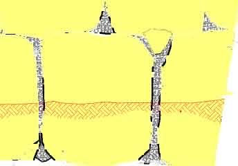
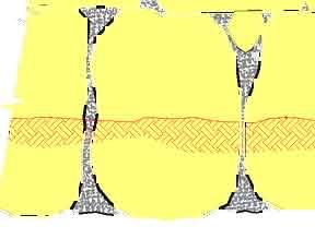

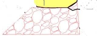
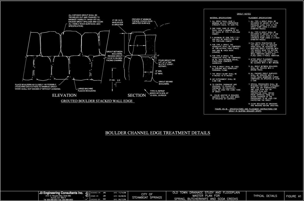
35
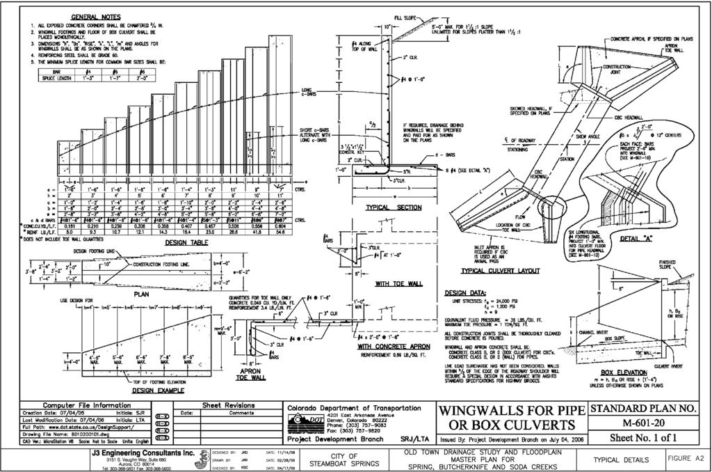
36
37
38
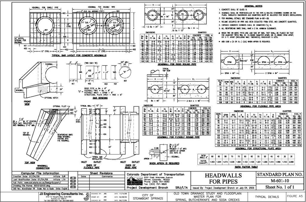
39
40
41
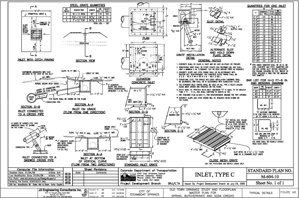
42
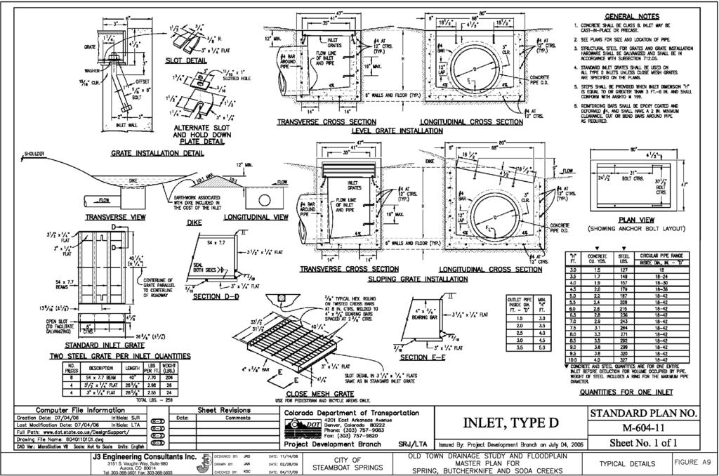
43

44
45 APPENDIX B: GENERAL FIGURES Old Town Drainage Study and Floodplain Masterplan for Soda, Butcherknife and Spring Creeks
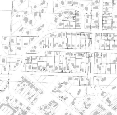
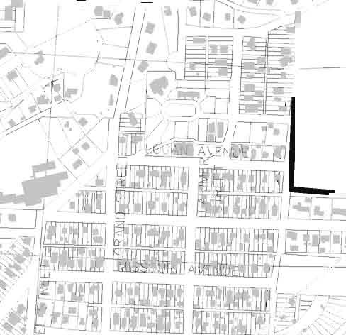

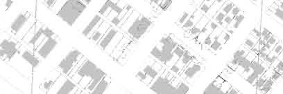
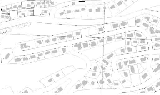
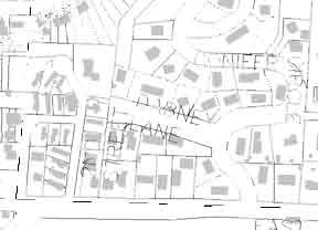
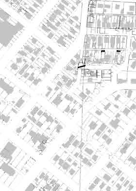
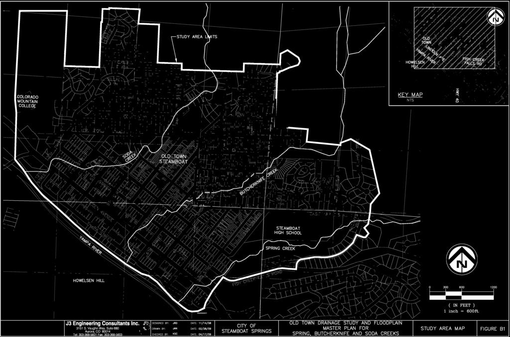
46


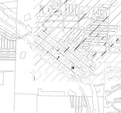
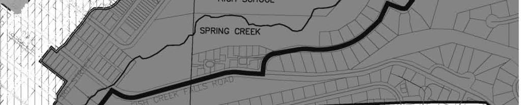

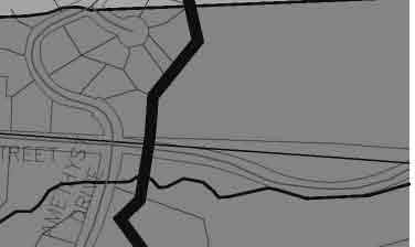
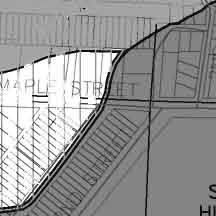
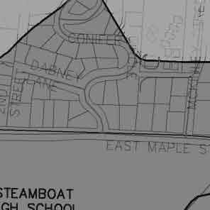
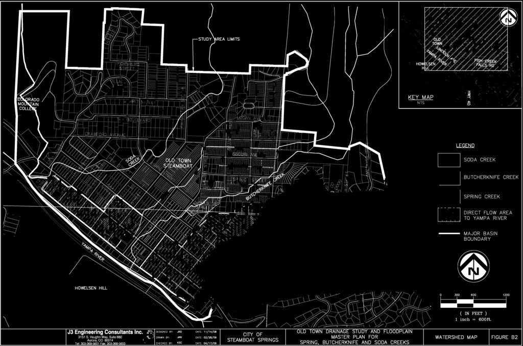
47
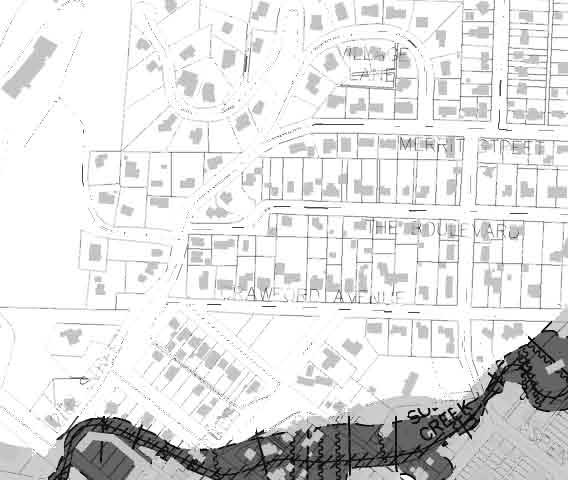
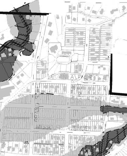

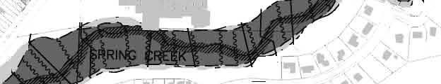
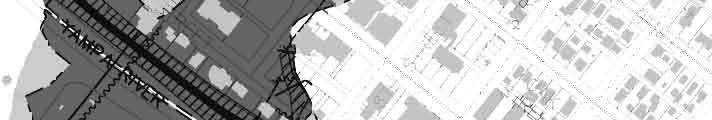
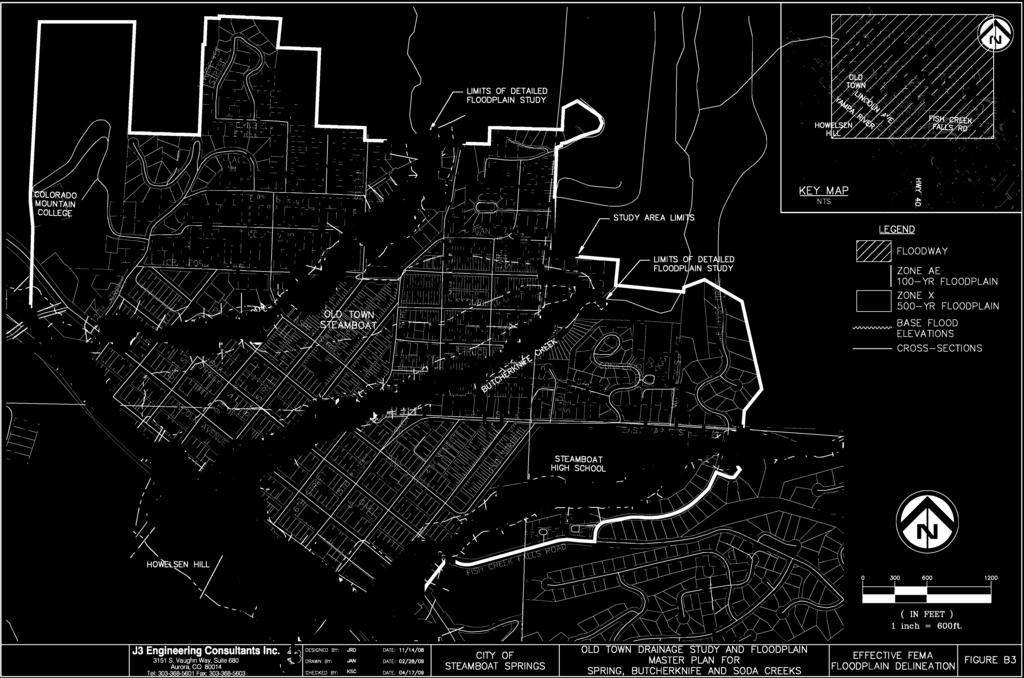
48
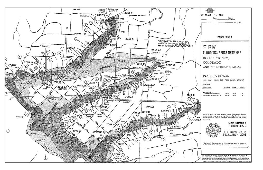
49 FIGURE B4
50 Soil Map Routt Area, Colorado, Parts of Rio Blanco and Routt Counties (Old Town Steamboat Springs) R CI A G 50C ST AL Y ST CRAWFO RD AVE ST H ST CO RTE 36 N LARIMER RD RI NG ST ST EE K LN MAPLE ST Steamboat Springs CI R SP 50C 3R D SH RR D OA K 6T ST BLUE SPRUCE DR BLUE SAG E CIR H 4T BL FISH CREEK FALLS RD CT 133 N PK W W B LU Y AG ES R ED U C LO ER W Y DR C H ER R PO ST C T SE GE 5T H SA ST EM ERAL CT UE EL CI Sp ring Cre ek ST AV E ST LN H O pa YA M Ri PA S ve T r HO W G RIN O RT ST H 8T Ya m EY D ABN 2N D 9T LI NC A FAI RVI E X2 5 ST JAM ES ST CR 68D 94 H 10 ST TH ST PI NE W WA VE SP HILL ST ST MANITO U ST 105 SPRUCE ST 7T N Creek MISSOURI AVE H 11 T 121 SARATOGA AVE PE ST ST TH 12 2ND AVE PITKIN ST CT 133 Bu tche rkn ife NE PI CT BEAR VIEW PITKIN ST AS So da Cree k LOG AN AVE MCK INLE Y EVANS ST LI TT PA G OS A ROUTT ST LE SP RI 12 NG TH RD E PARK AVE PI N 50C OA K RD CRAWFO RD AVE CRAWFO RD AVE OT ST D FO WO ODS DR LARI MER ST R N ST D M EA LA ER D 33 IS Z X25A ST RD PL THE BOULEVARD 50C COLLEG E DR LZ DE 2N 139 AV E PAHWINTAH ST VIL 133 GRA ND ST E DP LN 133 MERRITT ST LAUREL ST ID G AN CO 66F 49A YAHMO NITE RD I SL LA G BO BR LIN M OC K EA US E 68D ST N GRAND ST RT URG PO W ER LIN MS DA 50F BA DR CO RNB E 40 N PARK TH O US EL N AVE DR OL N 103 LINC BROAD ST CO N ES TO YST D R X8F N T RL A M E TH 50 E INDIA E N LI E US CO E 40 RT 14 OL Natural Resources Conservation Service , RD D FISHCRE EK L WI L OW CT R TA MA AC K DR Meters 600 2,000 Feet 3,000 Web Soil Survey 2.0 National Cooperative Soil Survey 11/10/2008 Page 1 of 3 FIGURE B5
51 FIGURE B6
52
53 Hydrologic Soil Group Routt Area, Colorado, Parts of Rio Blanco and Routt Counties (Old Town Steamboat Springs) R CI A G 50C ST AL Y ST CRAWFO RD AVE ST H ST CO RTE 36 N LARIMER RD RI NG ST ST EE K LN MAPLE ST Steamboat Springs CI R SP 50C 3R D SH RR D OA K 6T ST BLUE SPRUCE DR BLUE SAG E CIR H 4T BL FISH CREEK FALLS RD CT 133 N PK W W B LU Y AG ES R ED U C LO ER W Y DR C H ER R PO ST C T SE GE 5T H SA ST EM ERAL CT UE EL CI Sp ring Cre ek ST AV E ST LN H O pa YA M Ri PA S ve T r HO W G RIN O RT ST H 8T Ya m EY D ABN 2N D 9T LI NC A FAI RVI E X2 5 ST JAM ES ST CR 68D 94 H 10 ST TH ST PI NE W WA VE SP HILL ST ST MANITO U ST 105 SPRUCE ST 7T N Creek MISSOURI AVE H 11 T 121 SARATOGA AVE PE ST ST TH 12 2ND AVE PITKIN ST CT 133 Bu tche rkn ife NE PI CT BEAR VIEW PITKIN ST AS So da Cree k LOG AN AVE MCK INLE Y EVANS ST LI TT PA G OS A ROUTT ST LE SP RI 12 NG TH RD E PARK AVE PI N 50C OA K RD CRAWFO RD AVE CRAWFO RD AVE OT ST D FO WO ODS DR LARI MER ST R N ST D M EA LA ER D 33 IS Z X25A ST RD PL THE BOULEVARD 50C COLLEG E DR LZ DE 2N 139 AV E PAHWINTAH ST VIL 133 GRA ND ST E DP LN 133 MERRITT ST LAUREL ST ID G AN CO 66F 49A YAHMO NITE RD I SL LA G BO BR LIN M OC K EA US E 68D ST N GRAND ST RT URG PO W ER LIN MS DA 50F BA DR CO RNB E 40 N PARK TH O US EL N AVE DR OL N 103 LINC BROAD ST CO N ES TO YST D R X8F N T RL A M E TH 50 E INDIA E N LI E US CO E 40 RT 14 OL Natural Resources Conservation Service , RD D FISHCRE EK L WI L OW CT R TA MA AC K DR Meters 600 2,000 Feet 3,000 Web Soil Survey 2.0 National Cooperative Soil Survey 11/10/2008 Page 1 of 4 FIGURE B8
54 FIGURE B9
55

56 Wind Erodibility Group Routt Area, Colorado, Parts of Rio Blanco and Routt Counties (Old Town Steamboat Springs) R CI A G 50C ST AL Y ST CRAWFO RD AVE ST H ST CO RTE 36 N LARIMER RD RI NG ST ST EE K LN MAPLE ST Steamboat Springs CI R SP 50C 3R D SH RR D OA K 6T ST BLUE SPRUCE DR BLUE SAG E CIR H 4T BL FISH CREEK FALLS RD CT 133 N PK W W B LU Y AG ES R ED U C LO ER W Y DR C H ER R PO ST C T SE GE 5T H SA ST EM ERAL CT UE EL CI Sp ring Cre ek ST AV E ST LN H O pa YA M Ri PA S ve T r HO W G RIN O RT ST H 8T Ya m EY D ABN 2N D 9T LI NC A FAI RVI E X2 5 ST JAM ES ST CR 68D 94 H 10 ST TH ST PI NE W WA VE SP HILL ST ST MANITO U ST 105 SPRUCE ST 7T N Creek MISSOURI AVE H 11 T 121 SARATOGA AVE PE ST ST TH 12 2ND AVE PITKIN ST CT 133 Bu tche rkn ife NE PI CT BEAR VIEW PITKIN ST AS So da Cree k LOG AN AVE MCK INLE Y EVANS ST LI TT PA G OS A ROUTT ST LE SP RI 12 NG TH RD E PARK AVE PI N 50C OA K RD CRAWFO RD AVE CRAWFO RD AVE OT ST D FO WO ODS DR LARI MER ST R N ST D M EA LA ER D 33 IS Z X25A ST RD PL THE BOULEVARD 50C COLLEG E DR LZ DE 2N 139 AV E PAHWINTAH ST VIL 133 GRA ND ST E DP LN 133 MERRITT ST LAUREL ST ID G AN CO 66F 49A YAHMO NITE RD I SL LA G BO BR LIN M OC K EA US E 68D ST N GRAND ST RT URG PO W ER LIN MS DA 50F BA DR CO RNB E 40 N PARK TH O US EL N AVE DR OL N 103 LINC BROAD ST CO N ES TO YST D R X8F N T RL A M E TH 50 E INDIA E N LI E US CO E 40 RT 14 OL Natural Resources Conservation Service , RD D FISHCRE EK L WI L OW CT R TA MA AC K DR Meters 600 2,000 Feet 3,000 Web Soil Survey 2.0 National Cooperative Soil Survey 11/10/2008 Page 1 of 4 FIGURE B11
57 FIGURE B12
58

59 FIGURE B14
60 APPENDIX C: HYDROLOGIC ANALYSIS AND SUPPORTING DOCUMENTATION Old Town Drainage Study and Floodplain Masterplan for Soda, Butcherknife and Spring Creeks


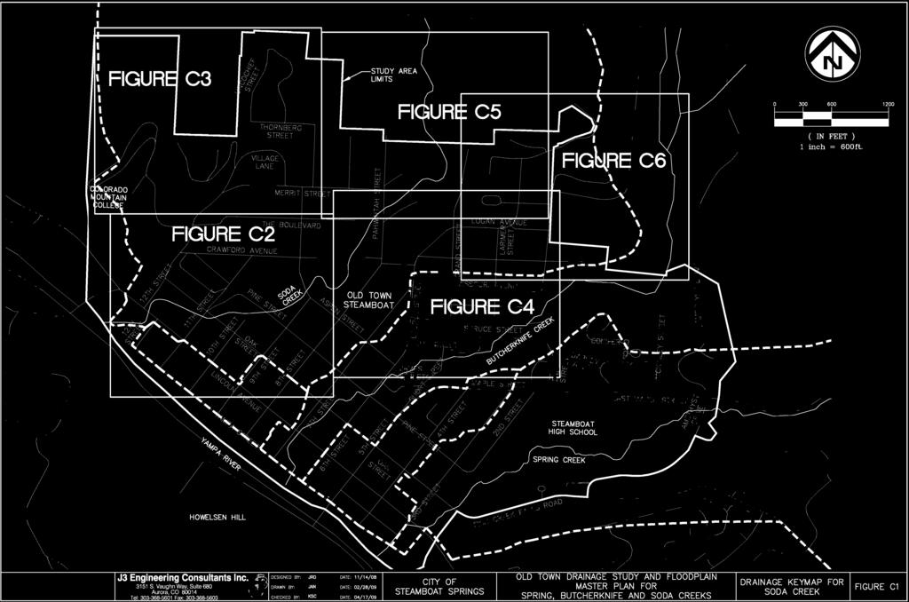
61
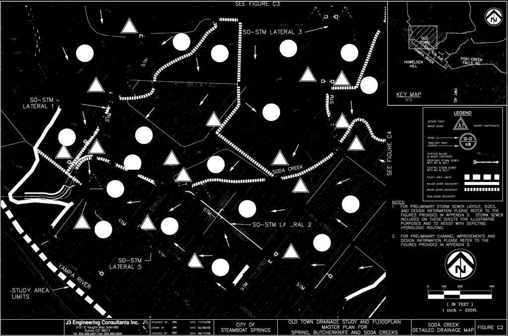
62
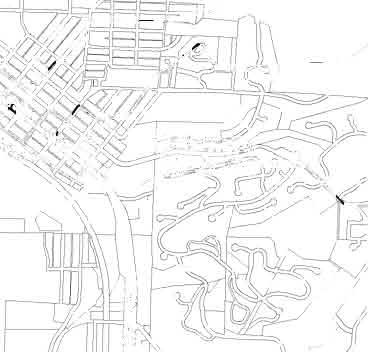
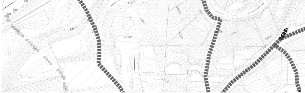
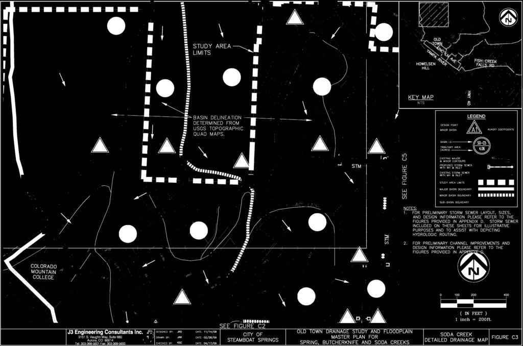
63
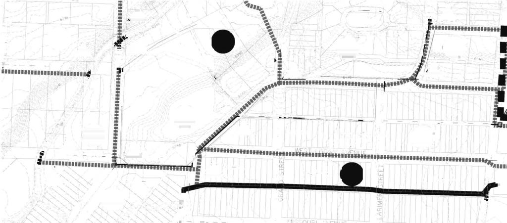
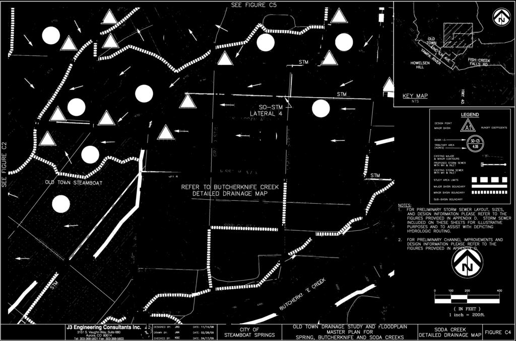
64
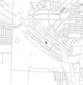
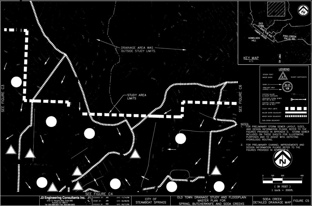
65
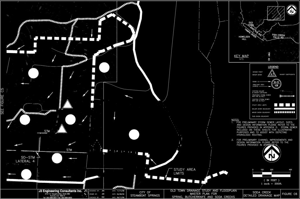
66

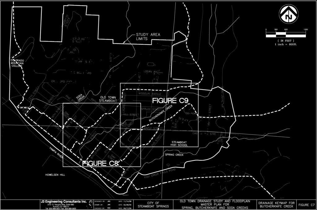
67
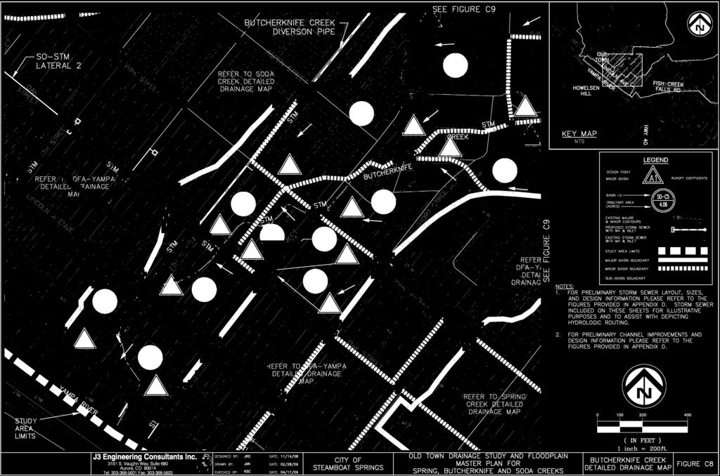
68
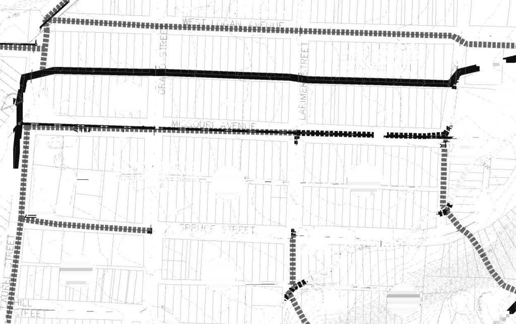
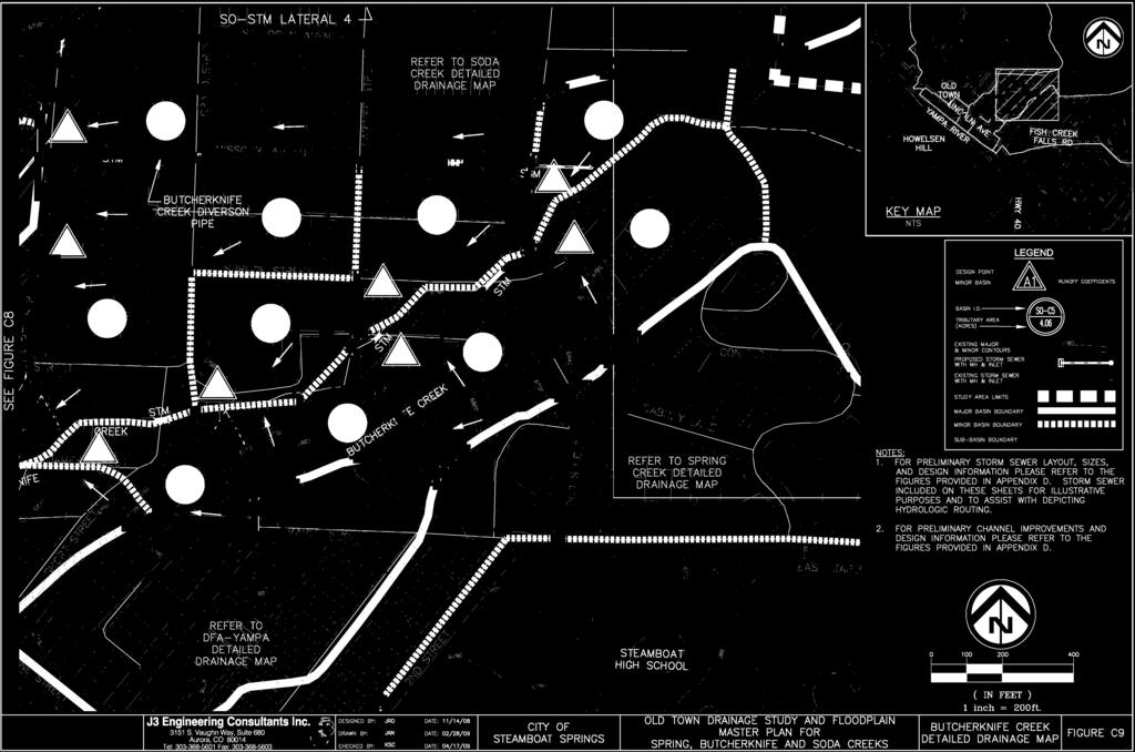
69


70
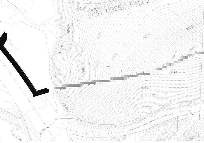
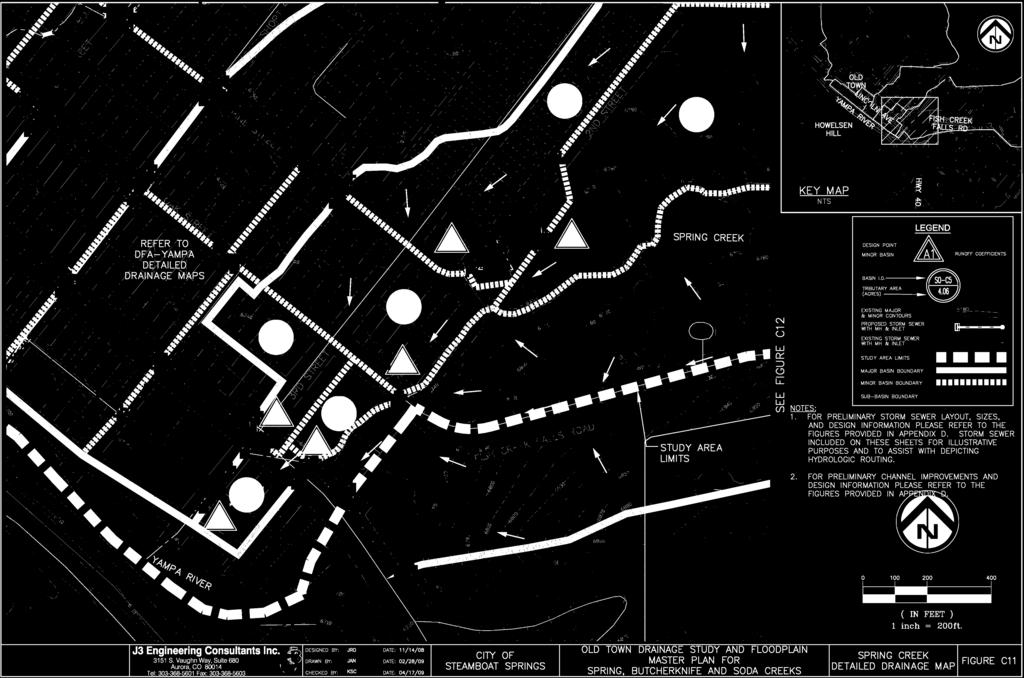
71
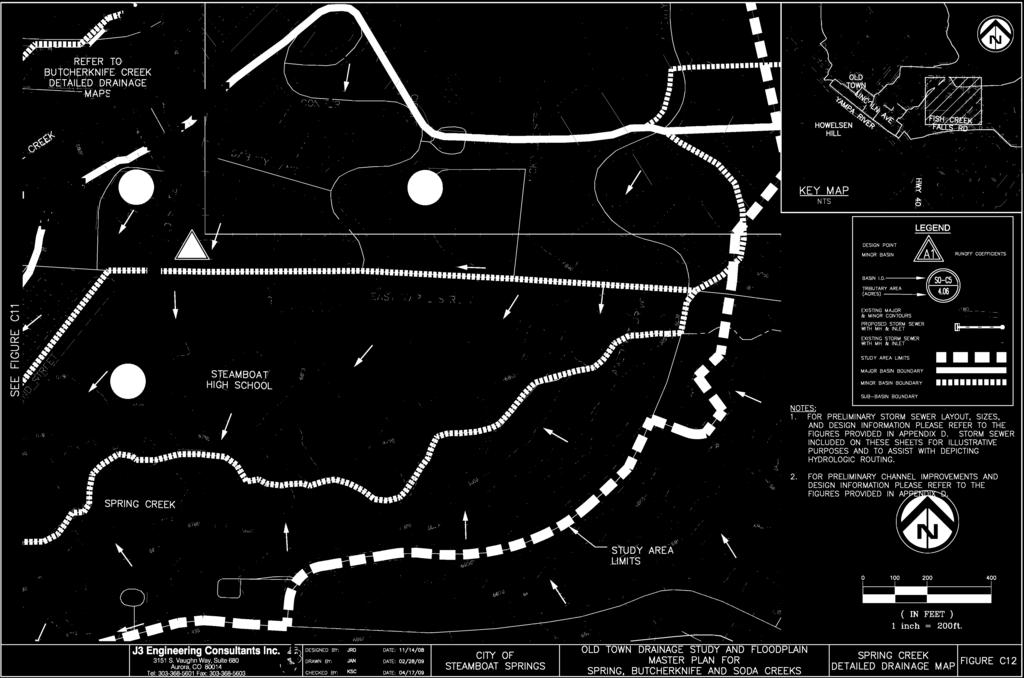
72

73
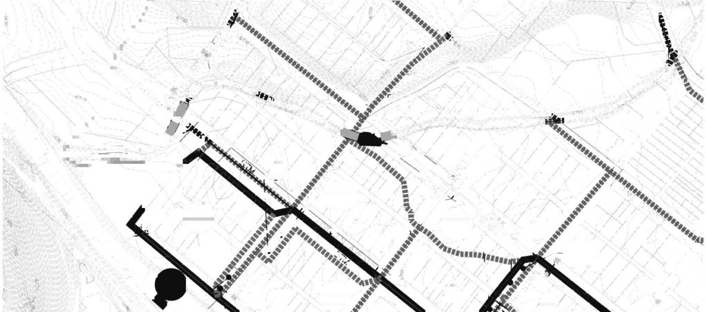
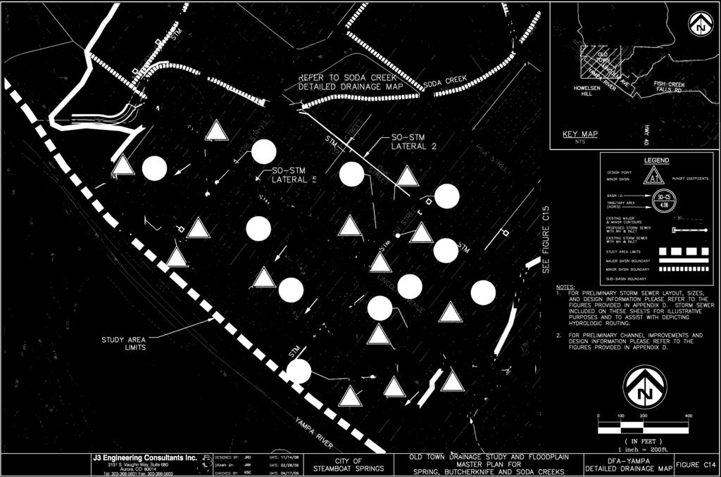
74
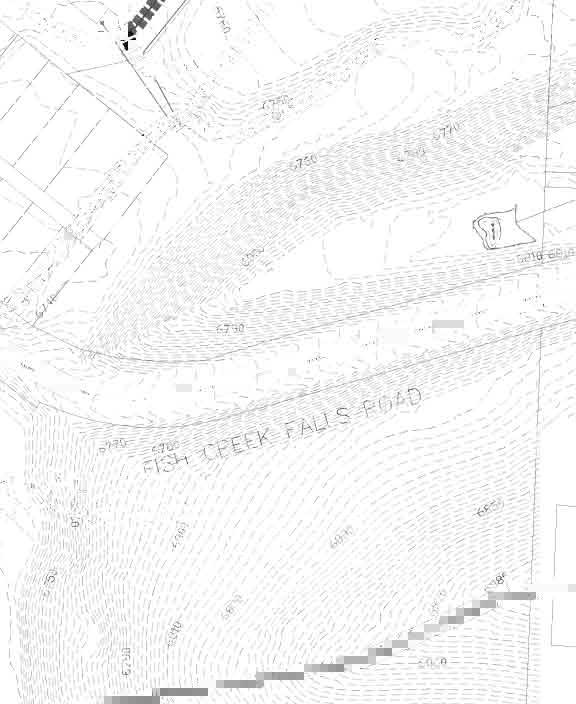
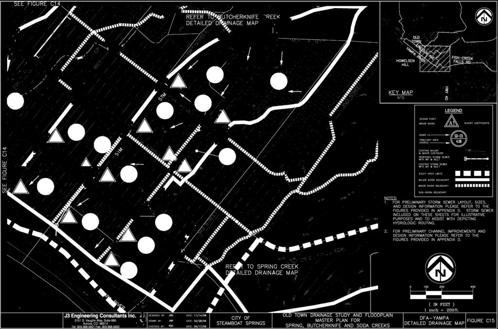
75
76 Old Town Drainage Study Rational Calculations Summary ~ SODA CREEK AND PORTIONS OF DFA - YAMPA Design Tributary Tributary 5 -Year 10 -Year 25 -Year 100 -Year Point Drainage Area Runoff Runoff Runoff Runoff (SO) Basins (acres) (cfs) (cfs) (cfs) (cfs) A1 A A2 A A3 A A4 A B1 B B2 B B3 B B3 B1, B2 & B B4 B B4 B1, B2, B3 & B B5 B B5 B1, B2, B3, B4 & B B6 B B6 B1, B2, B3, B4, B5 & B B7 B B8 B B8 B1, B2, B3, B4, B5, B6, B7 & B B9 B B10 B B10 B1, B2, B3, B4, B5, B6, B7, B8, B9 &B B11 B B11 B1, B2, B3, B4, B5, B6, B7, B8, B9, B10 & B C1 C C2 C C2 C1 & C C3 C C3 C1, C2, C6 & C C4 C C5 C C5 C1, C2, C3, C4, C5 & C C7 C C7 C1, C2, C3, C4, C5, C6 & C C6 C D1 D D2 D D2 D1 & D D3 D D4 D
77 Old Town Drainage Study Rational Calculations Summary ~ SODA CREEK AND PORTIONS OF DFA - YAMPA Design Tributary Tributary 5 -Year 10 -Year 25 -Year 100 -Year Point Drainage Area Runoff Runoff Runoff Runoff (SO) Basins (acres) (cfs) (cfs) (cfs) (cfs) E1 E E2 E F1 F F2 F F3 F F3 F1 & F F4 F F5 F F5 F1, F2, F3, F4, F5 & F F6 F F7 F F7 F1, F2, F3, F4, F5, F6 & F F8 F F8 F1, F2, F3, F4, F5, F6, F7 & F F9 F G1 G G2 G G3 G G4 G G4 G3 & G H1 H H2 H H2 H1 & H H3 H H3 H1, H2, H H4 H
78 Old Town Drainage Study Rational Calculations Summary ~ SODA CREEK AND PORTIONS OF DFA - YAMPA Design Tributary Tributary 5 -Year 10 -Year 25 -Year 100 -Year Point Drainage Area Runoff Runoff Runoff Runoff (SO) Basins (acres) (cfs) (cfs) (cfs) (cfs) (DFA) Y1 Y Y2 Y Y2 Y2 & Y Y3 Y Y4 Y Y2 Y2, Y3 & Y Y5 Y Y6 Y Y6 Y6 & Y Y7 Y Y8 Y Y8 Y6, Y7 & Y Y9 Y Y9 Y6, Y7, Y8 & Y Y10 Y Y10 Y6, Y7, Y8, Y9 & Y Y11 Y Y12 Y Y12 Y11 & Y Y13 Y Y13 Y11, Y12 & Y Y14 Y Y14 Y11, Y12, Y13 & Y Y15 Y P:\Jobs\Steamboat Springs\Old Town Masterplan\MasterPlan\Drainage Calculations\2nd Submittal\[SO_Old-Town_Rational.xls]Tc
79 Parcel Data Table Soda Creek and Portions of DFA - Yampa ` Job No.: Date: 2/27/2009 Calculated By: Checked By: JDM KSC Parcel Data Table Area Land Use Category Density (DU/acre) C5 C10 C25 C100 I (%) Comments ` Undeveloped Undeveloped Undeveloped Land ~ Historic Flow Analysis Commercial (on- & off-site) Commercial Commercial Areas Schools / Churches Schools & Churches Schools & Churches Residential 1 Single Family Detached Low Density Residential 2 Single Family Detached Medium Density Residential 3 Single Family Detached High Density Open Space Open Space, Park and Landscape Tracts Open Space, parks and landscape tracts *Percent Impervious values for the Residential land uses were generated off three sample blocks. Please see the attached exhibits for location and methodology. **Runoff Coefficients are from the City of Steamboat Springs Engineering Standards, Table Design Runoff Coefficients ***Percent Impervious Values for Undeveloped and Open Space have been increased to 5% P:\Jobs\Steamboat Springs\Old Town Masterplan\MasterPlan\Drainage Calculations\2nd Submittal\[SO_Old-Town_Rational.xls]Tc
80 Composite Imperviousness Calculations Soda Creek and Portions of DFA - Yampa City of Steamboat Springs, Colorado Job No.: Date: 2/27/09 Calculated By: JDM Checked By: KSC Parcel Imperviousness Major Basin Soda Creek A Sub-Basin Area Undeveloped Commercial (on- & off-site) Schools / Churches Residential 1 (acres) (%) A A A A Residential 2 Residential 3 Open Space Composite Imperviousness Sum B B B B B B B B B B B B Sum
81 Composite Imperviousness Calculations Soda Creek and Portions of DFA - Yampa City of Steamboat Springs, Colorado Job No.: Date: 2/27/09 Calculated By: JDM Checked By: KSC Parcel Imperviousness Major Basin Sub-Basin Area Undeveloped Commercial (on- & off-site) Schools / Churches Residential 1 (acres) (%) Residential 2 Residential 3 Open Space Composite Imperviousness C C C C C C C C Sum D D D D D Sum E E E Sum
82 Composite Imperviousness Calculations Soda Creek and Portions of DFA - Yampa City of Steamboat Springs, Colorado Job No.: Date: 2/27/09 Calculated By: JDM Checked By: KSC Parcel Imperviousness Major Basin Sub-Basin Area Undeveloped Commercial (on- & off-site) Schools / Churches Residential 1 (acres) (%) Residential 2 Residential 3 Open Space Composite Imperviousness F F F F F F F F F F Sum G G G G G Sum H H H H H Sum
83 Composite Imperviousness Calculations Soda Creek and Portions of DFA - Yampa City of Steamboat Springs, Colorado Job No.: Date: 2/27/09 Calculated By: JDM Checked By: KSC Parcel Imperviousness Major Basin Sub-Basin Area Undeveloped Commercial (on- & off-site) Schools / Churches Residential 1 (acres) (%) Residential 2 Residential 3 Open Space Composite Imperviousness Y Y Y Y Y Y Y Y Y Y Y Y Y Y Y Y Sum TOTAL Sum P:\Jobs\Steamboat Springs\Old Town Masterplan\MasterPlan\Drainage Calculations\2nd Submittal\[SO_Old-Town_Rational.xls]Tc
84 Composite "C" Calculations Soda Creek and Portions of DFA - Yampa City of Steamboat Springs, Colorado Job No.: Date: Calculated By: 2/27/09 JDM Checked By: KSC 2 Year Calculation Area Type 5 Year Calculation Area Type 10 Year Calculation Area Type 25 Year Calculation Area Type 100 Year Calculation Area Type Basin Sub-Basin Area (acres) Undeveloped Commercial (on- & off-site) Schools / Churches Residential 1 Residential 2 Residential 3 Open Space C2 Undeveloped Commercial (on- & off-site) Schools / Churches Residential 1 Residential 2 Residential 3 Open Space C5 Undeveloped Commercial (on- & off-site) Schools / Churches Residential 1 Residential 2 Residential 3 Open Space C10 Undeveloped Commercial (on- & off-site) Schools / Churches Residential 1 Residential 2 Residential 3 Open Space C10 Undeveloped Commercial (on- & off-site) Schools / Churches Residential 1 Residential 2 Residential 3 Open Space C100 A A A A A B B B B B B B B B B B B C C C C C C C C
85 Composite "C" Calculations Soda Creek and Portions of DFA - Yampa City of Steamboat Springs, Colorado Job No.: Date: Calculated By: 2/27/09 JDM Checked By: KSC 2 Year Calculation Area Type 5 Year Calculation Area Type 10 Year Calculation Area Type 25 Year Calculation Area Type 100 Year Calculation Area Type Basin Sub-Basin Area (acres) Undeveloped Commercial (on- & off-site) Schools / Churches Residential 1 Residential 2 Residential 3 Open Space C2 Undeveloped Commercial (on- & off-site) Schools / Churches Residential 1 Residential 2 Residential 3 Open Space C5 Undeveloped Commercial (on- & off-site) Schools / Churches Residential 1 Residential 2 Residential 3 Open Space C10 Undeveloped Commercial (on- & off-site) Schools / Churches Residential 1 Residential 2 Residential 3 Open Space C10 Undeveloped Commercial (on- & off-site) Schools / Churches Residential 1 Residential 2 Residential 3 Open Space C100 D D D D D E E E F F F F F F F F F F G G G G G
86 Composite "C" Calculations Soda Creek and Portions of DFA - Yampa City of Steamboat Springs, Colorado Job No.: Date: Calculated By: 2/27/09 JDM Checked By: KSC 2 Year Calculation Area Type 5 Year Calculation Area Type 10 Year Calculation Area Type 25 Year Calculation Area Type 100 Year Calculation Area Type Basin Sub-Basin Area (acres) Undeveloped Commercial (on- & off-site) Schools / Churches Residential 1 Residential 2 Residential 3 Open Space C2 Undeveloped Commercial (on- & off-site) Schools / Churches Residential 1 Residential 2 Residential 3 Open Space C5 Undeveloped Commercial (on- & off-site) Schools / Churches Residential 1 Residential 2 Residential 3 Open Space C10 Undeveloped Commercial (on- & off-site) Schools / Churches Residential 1 Residential 2 Residential 3 Open Space C10 Undeveloped Commercial (on- & off-site) Schools / Churches Residential 1 Residential 2 Residential 3 Open Space C100 H H H H H Y Y Y Y Y Y Y Y Y Y Y Y Y Y Y Y P:\Jobs\Steamboat Springs\Old Town Masterplan\MasterPlan\Drainage Calculations\2nd Submittal\[SO_Old-Town_Rational.xls]Tc
87 TIME OF CONCENTRATION Soda Creek and Portions of DFA - Yampa 2/27/2009 Job No.: Date: 2/27/09 Calculated By: JDM Checked By: KSC BASIN SUB-BASIN DATA INITIAL/OVERLAND TRAVEL TIME Rational Tc Check for Urban Catchments FINAL Tc TIME (Tc) (Tt) Tc CONVEYANCE DESIG: AREA C5 LENGTH SLOPE Ti LENGTH AVG. SLOPE Conv. VEL Tt COMP TOTAL Tc=(L/180)+10 REMARKS (acres) (ft) (ft/ft) (min) (ft) DY (%) Type* (fps) (min) Tc (min) LENGTH (ft) (min) (min) A A Grass Swale A Grass Swale A Grass Swale A Pasture B B Grass Swale B Grass Swale B Grass Swale B Grass Swale B Grass Swale B Grass Swale B Grass Swale B Grass Swale B Grass Swale B Grass Swale B Pasture
88 TIME OF CONCENTRATION Soda Creek and Portions of DFA - Yampa 2/27/2009 Job No.: Date: 2/27/09 Calculated By: JDM Checked By: KSC BASIN SUB-BASIN DATA INITIAL/OVERLAND TRAVEL TIME Rational Tc Check for Urban Catchments FINAL Tc TIME (Tc) (Tt) Tc CONVEYANCE DESIG: AREA C5 LENGTH SLOPE Ti LENGTH AVG. SLOPE Conv. VEL Tt COMP TOTAL Tc=(L/180)+10 REMARKS (acres) (ft) (ft/ft) (min) (ft) DY (%) Type* (fps) (min) Tc (min) LENGTH (ft) (min) (min) C C Grass Swale C Grass Swale C Grass Swale C Grass Swale C Grass Swale C Grass Swale C Grass Swale D D Grass Swale D Paved Gutter D Paved Gutter D Paved Gutter E E Grass Swale E Grass Swale
89 TIME OF CONCENTRATION Soda Creek and Portions of DFA - Yampa 2/27/2009 Job No.: Date: 2/27/09 Calculated By: JDM Checked By: KSC BASIN SUB-BASIN DATA INITIAL/OVERLAND TRAVEL TIME Rational Tc Check for Urban Catchments FINAL Tc TIME (Tc) (Tt) Tc CONVEYANCE DESIG: AREA C5 LENGTH SLOPE Ti LENGTH AVG. SLOPE Conv. VEL Tt COMP TOTAL Tc=(L/180)+10 REMARKS (acres) (ft) (ft/ft) (min) (ft) DY (%) Type* (fps) (min) Tc (min) LENGTH (ft) (min) (min) F F Grass Swale F Grass Swale F Grass Swale F Grass Swale F Paved Gutter F Paved Gutter F Grass Swale F Grass Swale F Pasture G G Paved Gutter G Paved Gutter G Paved Gutter G Paved Gutter H H Paved Gutter H Paved Gutter H Paved Gutter H Paved Gutter
90 TIME OF CONCENTRATION Soda Creek and Portions of DFA - Yampa 2/27/2009 Job No.: Date: 2/27/09 Calculated By: JDM Checked By: KSC BASIN SUB-BASIN DATA INITIAL/OVERLAND TRAVEL TIME Rational Tc Check for Urban Catchments FINAL Tc TIME (Tc) (Tt) Tc CONVEYANCE DESIG: AREA C5 LENGTH SLOPE Ti LENGTH AVG. SLOPE Conv. VEL Tt COMP TOTAL Tc=(L/180)+10 REMARKS (acres) (ft) (ft/ft) (min) (ft) DY (%) Type* (fps) (min) Tc (min) LENGTH (ft) (min) (min) Y Y Paved Gutter Y Paved Gutter Y Paved Gutter Y Paved Gutter Y Paved Gutter Y Paved Gutter Y Paved Gutter Y Paved Gutter Y Paved Gutter Y Paved Gutter Y Paved Gutter Y Paved Gutter Y Paved Gutter Y Paved Gutter Y Paved Gutter * Note: Conveyance Coefficients - Type 1-Heavy Meadow, Type 2-Tillage/field, Type 3-Short Pasture & Lawn, J3 Engineering Consultants, Inc. Type 4-Nearly Bare Ground, Type 5-Grassed Waterway, Type 6-Paved Areas & Shallow Paved Swales. P:\Jobs\Steamboat Springs\Old Town Masterplan\MasterPlan\Drainage Calculations\2nd Submittal\[SO_Old-Town_Rational.xls]Tc
91 STANDARD FORM SF-2 STORM DRAINAGE SYSTEM DESIGN 5-year P1 = 0.78 (RATIONAL METHOD PROCEDURE) DESIGN STORM: 5-YEAR (minor storm) 10-year P1 = 0.94 CALCULATED BY: JDM PROJECT: Old Town Drainage Study JOB NO: 25-year P1 = 1.09 CHECKED BY: KSC MAJOR BASIN: Soda Creek and Portions of DFA - Yampa LOCATION: City of Steamboat Springs, Colorado 100-year P1 = 1.46 DIRECT RUNOFF TOTAL RUNOFF STREET PIPE TRAVEL TIME LOCATION DESIGN POINT AREA DESIG. AREA (Acres) RUNOFF COEFF Tc (min) C A (Acres) I (in/hour) Q (cfs) Tc (min) (C A) (Acres) I (in/hour) Q (cfs) SLOPE (%) STREET FLOW (cfs) DESIGN FLOW (cfs) SLOPE (%) PIPE SIZE LENGTH (ft) VELOCITY (fps) Tt (min) REMARKS Sub-basin A A1 A Direct runoff to DP A1 & Soda Creek A2 A Direct Runoff to DP A2 & Soda Creek A3 A Direct Runoff to DP A3 & Soda Creek A4 A Direct Runoff to DP A4 & Soda Creek Sub-basin B B1 B Direct runoff to DP B1 Ditch flow to DP B3 B2 B Direct runoff to DP B2 Ditch flow to DP B3 B3 B Direct runoff to DP B3 B3 B1, B2 & B Combine flow at DP B3 Ditch Flow to DP B4 B4 B Direct Runoff to DP B4 B4 B1, B2, B3 & B Combine flow at DP B4 Ditch Flow to DP B7 B5 B Direct Runoff to DP B5 B5 B1, B2, B3, B4 & B Combine flow at DP B5 Ditch Flow to DP B6 B6 B Direct runoff to DP B6 B6 B1, B2, B3, B4, B5 & B Combine flow at DP B6 Ditch Flow to DP B8 B7 B Direct runoff to DP B7 Ditch Flow to DP B10 B8 B Direct runoff to DP B8 B1, B2, B3, B4, B5, B6, B7 & B8 B Combine flow at DP B8 Ditch Flow to DP B10 B9 B Direct runoff to DP B9 B10 B Direct runoff to DP B10 B1, B2, B3, B4, B5, B6, B7, B10 B8, B9 &B Combine flow at DP B10 Ditch Flow to DP B11 B11 B Direct runoff to DP B11 B1, B2, B3, B4, B5, B6, B7, B11 B8, B9, B10 & B Combine flow at DP B11
92 STANDARD FORM SF-2 STORM DRAINAGE SYSTEM DESIGN 5-year P1 = 0.78 (RATIONAL METHOD PROCEDURE) DESIGN STORM: 5-YEAR (minor storm) 10-year P1 = 0.94 CALCULATED BY: JDM PROJECT: Old Town Drainage Study JOB NO: 25-year P1 = 1.09 CHECKED BY: KSC MAJOR BASIN: Soda Creek and Portions of DFA - Yampa LOCATION: City of Steamboat Springs, Colorado 100-year P1 = 1.46 DIRECT RUNOFF TOTAL RUNOFF STREET PIPE TRAVEL TIME LOCATION DESIGN POINT AREA DESIG. AREA (Acres) RUNOFF COEFF Tc (min) C A (Acres) I (in/hour) Q (cfs) Tc (min) (C A) (Acres) I (in/hour) Q (cfs) SLOPE (%) STREET FLOW (cfs) DESIGN FLOW (cfs) SLOPE (%) PIPE SIZE LENGTH (ft) VELOCITY (fps) Tt (min) REMARKS Sub-basin C C1 C Direct runoff to DP C1 Ditch flow to DP C2 C2 C Direct runoff to DP C2 C2 C1 & C Combine flow at DP C2 Ditch flow to DP C3 C3 C Direct runoff to DP C3 C3 C1, C2, C6 & C Combine flow at DP C3 Ditch flow to DP C4 C4 C Direct runoff to DP C4 C5 C Direct runoff to DP C5 C5 C1, C2, C3, C4, C5 & C Combine flow at DP C5 Ditch flow to DP C7 C7 C Direct runoff to DP C7 C7 C1, C2, C3, C4, C5, C6 & C Combine flow at DP C7 Pipe outfall to Soda Creek C6 C Direct runoff at DP C6 Sub-basin D D1 D Direct runoff at DP D1 Ditch flow to DP D2 D2 D Direct runoff at DP D2 D2 D1 & D Combine flow at DP D2 Outfall to Soda Creek D3 D Direct runoff at DP D3 Outfall to Soda Creek D4 D Direct runoff at DP D4 Sub-basin E E1 E Direct runoff at DP E1 Direct Discharge to Soda Creek E2 E Direct runoff at DP E2
93 STANDARD FORM SF-2 STORM DRAINAGE SYSTEM DESIGN 5-year P1 = 0.78 (RATIONAL METHOD PROCEDURE) DESIGN STORM: 5-YEAR (minor storm) 10-year P1 = 0.94 CALCULATED BY: JDM PROJECT: Old Town Drainage Study JOB NO: 25-year P1 = 1.09 CHECKED BY: KSC MAJOR BASIN: Soda Creek and Portions of DFA - Yampa LOCATION: City of Steamboat Springs, Colorado 100-year P1 = 1.46 DIRECT RUNOFF TOTAL RUNOFF STREET PIPE TRAVEL TIME LOCATION DESIGN POINT AREA DESIG. AREA (Acres) RUNOFF COEFF Tc (min) C A (Acres) I (in/hour) Q (cfs) Tc (min) (C A) (Acres) I (in/hour) Q (cfs) SLOPE (%) STREET FLOW (cfs) DESIGN FLOW (cfs) SLOPE (%) PIPE SIZE LENGTH (ft) VELOCITY (fps) Tt (min) REMARKS Sub-basin F F1 F Direct runoff at DP F1 Pipe flow to DP F3 F2 F Direct runoff at DP F2 Ditch flow to DP F5 F3 F Direct runoff at DP F3 F3 F1 & F Combine flow at DP F3 Pipe flow to DP F5 F4 F Direct runoff at DP F4 Pipe flow to DP F5 F5 F Direct runoff at DP F5 F5 F1, F2, F3, F4, F5 & F Combine flow at DP F5 Pipe flow to DP F7 F6 F Direct runoff at DP F6 F7 F Direct runoff at DP F7 F7 F1, F2, F3, F4, F5, F6 & F Combine flow at DP F7 Ditch flow to DP F8 F8 F Direct runoff at DP F8 F1, F2, F3, F4, F5, F6, F7 & F8 F Combine flow at DP F8 Direct Discharge to Soda Creek F9 F Direct runoff at DP F9 Sub-basin G G1 G Direct runoff at DP G1 Direct Discharge to Soda Creek G2 G Direct runoff at DP G2 Direct Discharge to Soda Creek G3 G Direct runoff to DP G3 Curb flow to DP G4 G4 G Direct runoff to DP G4 G4 G3 & G Combine flow at DP G4
94 STANDARD FORM SF-2 STORM DRAINAGE SYSTEM DESIGN 5-year P1 = 0.78 (RATIONAL METHOD PROCEDURE) DESIGN STORM: 5-YEAR (minor storm) 10-year P1 = 0.94 CALCULATED BY: JDM PROJECT: Old Town Drainage Study JOB NO: 25-year P1 = 1.09 CHECKED BY: KSC MAJOR BASIN: Soda Creek and Portions of DFA - Yampa LOCATION: City of Steamboat Springs, Colorado 100-year P1 = 1.46 DIRECT RUNOFF TOTAL RUNOFF STREET PIPE TRAVEL TIME LOCATION DESIGN POINT AREA DESIG. AREA (Acres) RUNOFF COEFF Tc (min) C A (Acres) I (in/hour) Q (cfs) Tc (min) (C A) (Acres) I (in/hour) Q (cfs) SLOPE (%) STREET FLOW (cfs) DESIGN FLOW (cfs) SLOPE (%) PIPE SIZE LENGTH (ft) VELOCITY (fps) Tt (min) REMARKS Sub-basin H H1 H Direct runoff at DP H1 Pipe Flow to DP H2 H2 H Direct runoff at DP H2 H2 H1 & H Combine Flow at DP H2 Pipe flow to DP H3 H3 H Direct runoff at DP H3 H3 H1, H2, H Combine Flow at DP H3 Direct Discharge to Soda Creek H4 H Sub-basin Y Y1 Y Direct Runoff at DP Y1 Y2 Y Direct Runoff at DP Y2 Y2 Y2 & Y Y3 Y Direct Runoff at DP Y3 Pipe flow to Y2 Y4 Y Direct Runoff at DP Y4 Y2 Y2, Y3 & Y Combine Flow at DP Y2 Direct Discharge to Yampa River Y5 Y Direct Runoff at DP Y5 Y6 Y Direct Runoff at DP Y6 Y6 Y6 & Y Combine flow at DP Y6 Pipe flow to DP Y8 Y7 Y Direct Runoff at DP Y7 Pipe flow to DP Y6 Y8 Y Direct Runoff at DP Y8 Y8 Y6, Y7 & Y Combine Flow at DP Y8 Pipe flow to DP Y9 Y9 Y9 Y Direct Runoff at DP Y9 Y9 Y6, Y7, Y8 & Y Combine Flow at DP Y9 Pipe flow to DP Y10 Y10 Y Direct runoff to DP Y10 Y10 Y6, Y7, Y8, Y9 & Y Combine Flow at DP Y10 Direct Discharge to Yampa River
95 STANDARD FORM SF-2 STORM DRAINAGE SYSTEM DESIGN 5-year P1 = 0.78 (RATIONAL METHOD PROCEDURE) DESIGN STORM: 5-YEAR (minor storm) 10-year P1 = 0.94 CALCULATED BY: JDM PROJECT: Old Town Drainage Study JOB NO: 25-year P1 = 1.09 CHECKED BY: KSC MAJOR BASIN: Soda Creek and Portions of DFA - Yampa LOCATION: City of Steamboat Springs, Colorado 100-year P1 = 1.46 DIRECT RUNOFF TOTAL RUNOFF STREET PIPE TRAVEL TIME LOCATION DESIGN POINT AREA DESIG. AREA (Acres) RUNOFF COEFF Tc (min) C A (Acres) I (in/hour) Q (cfs) Tc (min) (C A) (Acres) I (in/hour) Q (cfs) SLOPE (%) STREET FLOW (cfs) DESIGN FLOW (cfs) SLOPE (%) PIPE SIZE LENGTH (ft) VELOCITY (fps) Tt (min) REMARKS Y11 Y Direct Runoff at DP Y11 Pipe flow to DP Y12 Y12 Y Direct Flow to DP Y12 Y12 Y11 & Y Combine flow at DP Y12 Pipe flow to DP Y13 Y13 Y Direct runoff to DP Y13 Y13 Y11, Y12 & Y Combine flow at DP Y13 Pipe flow to DP Y14 Y14 Y14 Y Direct Runoff at DP Y14 Y14 Y11, Y12, Y13 & Y Combine flow at DP Y14 Direct Discharge to Yampa River Y15 Y Direct flow at DP Y15 Pipe flow to DP Y14 P:\Jobs\Steamboat Springs\Old Town Masterplan\MasterPlan\Drainage Calculations\2nd Submittal\[SO_Old-Town_Rational.xls]Tc J3 Engineering Consultants, Inc. Notes: Intensity -Duration Curve for Rational Method per equation RA-3 (Urban Drainage) I = (28.5*P1) / (10+Tc)^.786
96 STANDARD FORM SF-2 STORM DRAINAGE SYSTEM DESIGN 5-year P1 = 0.78 (RATIONAL METHOD PROCEDURE) DESIGN STORM: 10-YEAR 10-year P1 = 0.94 CALCULATED BY: JDM PROJECT: Old Town Drainage Study JOB NO: 25-year P1 = 1.09 CHECKED BY: KSC MAJOR BASIN: Soda Creek and Portions of DFA - Yampa LOCATION: Soda Creek and Portions of DFA - Yampa 100-year P1 = 1.46 DIRECT RUNOFF TOTAL RUNOFF STREET PIPE TRAVEL TIME LOCATION DESIGN POINT AREA DESIG. AREA (Acres) RUNOFF COEFF Tc (min) C A (Acres) I (in/hour) Q (cfs) Tc (min) (C A) (Acres) I (in/hour) Q (cfs) SLOPE (%) STREET FLOW (cfs) DESIGN FLOW (cfs) SLOPE (%) PIPE SIZE LENGTH (ft) VELOCITY (fps) Tt (min) REMARKS Sub-basin A A1 A Direct runoff to DP A1 & Soda Creek A2 A Direct Runoff to DP A2 & Soda Creek A3 A Direct Runoff to DP A3 & Soda Creek A4 A Direct Runoff to DP A4 & Soda Creek Sub-basin B B1 B Direct runoff to DP B1 Ditch flow to DP B3 B2 B Direct runoff to DP B2 Ditch flow to DP B3 B3 B Direct runoff to DP B3 B3 B1, B2 & B Combine flow at DP B3 Ditch Flow to DP B4 B4 B Direct Runoff to DP B4 B4 B1, B2, B3 & B Combine flow at DP B4 Ditch Flow to DP B7 B5 B Direct Runoff to DP B5 B5 B1, B2, B3, B4 & B Combine flow at DP B5 Ditch Flow to DP B6 B6 B Direct runoff to DP B6 B6 B1, B2, B3, B4, B5 & B Combine flow at DP B6 Ditch Flow to DP B8 B7 B Direct runoff to DP B7 Ditch Flow to DP B10 B8 B Direct runoff to DP B8 B1, B2, B3, B4, B5, B6, B7 & B8 B Combine flow at DP B8 Ditch Flow to DP B10 B9 B Direct runoff to DP B9 B10 B Direct runoff to DP B10 B1, B2, B3, B4, B5, B6, B7, B10 B8, B9 &B Combine flow at DP B10 Ditch Flow to DP B11 B11 B Direct runoff to DP B11 B1, B2, B3, B4, B5, B6, B7, B11 B8, B9, B10 & B Combine flow at DP B11
97 STANDARD FORM SF-2 STORM DRAINAGE SYSTEM DESIGN 5-year P1 = 0.78 (RATIONAL METHOD PROCEDURE) DESIGN STORM: 10-YEAR 10-year P1 = 0.94 CALCULATED BY: JDM PROJECT: Old Town Drainage Study JOB NO: 25-year P1 = 1.09 CHECKED BY: KSC MAJOR BASIN: Soda Creek and Portions of DFA - Yampa LOCATION: Soda Creek and Portions of DFA - Yampa 100-year P1 = 1.46 DIRECT RUNOFF TOTAL RUNOFF STREET PIPE TRAVEL TIME LOCATION DESIGN POINT AREA DESIG. AREA (Acres) RUNOFF COEFF Tc (min) C A (Acres) I (in/hour) Q (cfs) Tc (min) (C A) (Acres) I (in/hour) Q (cfs) SLOPE (%) STREET FLOW (cfs) DESIGN FLOW (cfs) SLOPE (%) PIPE SIZE LENGTH (ft) VELOCITY (fps) Tt (min) REMARKS Sub-basin C C1 C Direct runoff to DP C1 Ditch flow to DP C2 C2 C Direct runoff to DP C2 C2 C1 & C Combine flow at DP C2 Ditch flow to DP C3 C3 C Direct runoff to DP C3 C3 C1, C2, C6 & C Combine flow at DP C3 Ditch flow to DP C4 C4 C Direct runoff to DP C4 C5 C Direct runoff to DP C5 C5 C1, C2, C3, C4, C5 & C Combine flow at DP C5 Ditch flow to DP C7 C7 C Direct runoff to DP C7 C7 C1, C2, C3, C4, C5, C6 & C Combine flow at DP C7 Pipe outfall to Soda Creek C6 C Direct runoff at DP C6 Sub-basin D D1 D Direct runoff at DP D1 Ditch flow to DP D2 D2 D Direct runoff at DP D2 D2 D1 & D Combine flow at DP D2 Outfall to Soda Creek D3 D Direct runoff at DP D3 Outfall to Soda Creek D4 D Direct runoff at DP D4 Sub-basin E E1 E Direct runoff at DP E1 Direct Discharge to Soda Creek E2 E Direct runoff at DP E2
98 STANDARD FORM SF-2 STORM DRAINAGE SYSTEM DESIGN 5-year P1 = 0.78 (RATIONAL METHOD PROCEDURE) DESIGN STORM: 10-YEAR 10-year P1 = 0.94 CALCULATED BY: JDM PROJECT: Old Town Drainage Study JOB NO: 25-year P1 = 1.09 CHECKED BY: KSC MAJOR BASIN: Soda Creek and Portions of DFA - Yampa LOCATION: Soda Creek and Portions of DFA - Yampa 100-year P1 = 1.46 DIRECT RUNOFF TOTAL RUNOFF STREET PIPE TRAVEL TIME LOCATION DESIGN POINT AREA DESIG. AREA (Acres) RUNOFF COEFF Tc (min) C A (Acres) I (in/hour) Q (cfs) Tc (min) (C A) (Acres) I (in/hour) Q (cfs) SLOPE (%) STREET FLOW (cfs) DESIGN FLOW (cfs) SLOPE (%) PIPE SIZE LENGTH (ft) VELOCITY (fps) Tt (min) REMARKS Sub-basin F F1 F Direct runoff at DP F1 Pipe flow to DP F3 F2 F Direct runoff at DP F2 Ditch flow to DP F5 F3 F Direct runoff at DP F3 F3 F1 & F Combine flow at DP F3 Pipe flow to DP F5 F4 F Direct runoff at DP F4 Pipe flow to DP F5 F5 F Direct runoff at DP F5 F5 F1, F2, F3, F4, F5 & F Combine flow at DP F5 Pipe flow to DP F7 F6 F Direct runoff at DP F6 F7 F Direct runoff at DP F7 F7 F1, F2, F3, F4, F5, F6 & F Combine flow at DP F7 Ditch flow to DP F8 F8 F Direct runoff at DP F8 F1, F2, F3, F4, F5, F6, F7 & F8 F Combine flow at DP F8 Direct Discharge to Soda Creek F9 F Direct runoff at DP F9 Sub-basin G G1 G Direct runoff at DP G1 Direct Discharge to Soda Creek G2 G Direct runoff at DP G2 Direct Discharge to Soda Creek G3 G Direct runoff to DP G3 Curb flow to DP G4 G4 G Direct runoff to DP G4 G4 G3 & G Combine flow at DP G4
99 STANDARD FORM SF-2 STORM DRAINAGE SYSTEM DESIGN 5-year P1 = 0.78 (RATIONAL METHOD PROCEDURE) DESIGN STORM: 10-YEAR 10-year P1 = 0.94 CALCULATED BY: JDM PROJECT: Old Town Drainage Study JOB NO: 25-year P1 = 1.09 CHECKED BY: KSC MAJOR BASIN: Soda Creek and Portions of DFA - Yampa LOCATION: Soda Creek and Portions of DFA - Yampa 100-year P1 = 1.46 DIRECT RUNOFF TOTAL RUNOFF STREET PIPE TRAVEL TIME LOCATION DESIGN POINT AREA DESIG. AREA (Acres) RUNOFF COEFF Tc (min) C A (Acres) I (in/hour) Q (cfs) Tc (min) (C A) (Acres) I (in/hour) Q (cfs) SLOPE (%) STREET FLOW (cfs) DESIGN FLOW (cfs) SLOPE (%) PIPE SIZE LENGTH (ft) VELOCITY (fps) Tt (min) REMARKS Sub-basin H H1 H Direct runoff at DP H1 Pipe Flow to DP H2 H2 H Direct runoff at DP H2 H2 H1 & H Combine Flow at DP H2 Pipe flow to DP H3 H3 H Direct runoff at DP H3 H Combine Flow at DP H3 Direct Discharge to Soda Creek H4 H Sub-basin Y Y1 Y Direct Runoff at DP Y1 Y2 Y Direct Runoff at DP Y2 Y2 Y2 & Y Y3 Y Direct Runoff at DP Y3 Pipe flow to Y2 Y4 Y Direct Runoff at DP Y4 Y2 Y2, Y3 & Y Combine Flow at DP Y2 Direct Discharge to Yampa River Y5 Y Direct Runoff at DP Y5 Y6 Y Direct Runoff at DP Y6 Y6 Y6 & Y Combine flow at DP Y6 Pipe flow to DP Y8 Y7 Y Direct Runoff at DP Y7 Pipe flow to DP Y6 Y8 Y Direct Runoff at DP Y8 Y8 Y6, Y7 & Y Combine Flow at DP Y8 Pipe flow to DP Y9 Y9 Y9 Y Direct Runoff at DP Y9 Y9 Y6, Y7, Y8 & Y Combine Flow at DP Y9 Pipe flow to DP Y10 Y10 Y Direct runoff to DP Y10 Y10 Y6, Y7, Y8, Y9 & Y Combine Flow at DP Y10 Direct Discharge to Yampa River Y11 Y Direct Runoff at DP Y11
100 STANDARD FORM SF-2 STORM DRAINAGE SYSTEM DESIGN 5-year P1 = 0.78 (RATIONAL METHOD PROCEDURE) DESIGN STORM: 10-YEAR 10-year P1 = 0.94 CALCULATED BY: JDM PROJECT: Old Town Drainage Study JOB NO: 25-year P1 = 1.09 CHECKED BY: KSC MAJOR BASIN: Soda Creek and Portions of DFA - Yampa LOCATION: Soda Creek and Portions of DFA - Yampa 100-year P1 = 1.46 DIRECT RUNOFF TOTAL RUNOFF STREET PIPE TRAVEL TIME LOCATION DESIGN POINT AREA DESIG. AREA (Acres) RUNOFF COEFF Tc (min) C A (Acres) I (in/hour) Q (cfs) Tc (min) (C A) (Acres) I (in/hour) Q (cfs) SLOPE (%) STREET FLOW (cfs) DESIGN FLOW (cfs) SLOPE (%) PIPE SIZE LENGTH (ft) VELOCITY (fps) Tt (min) REMARKS Pipe flow to DP Y12 Y12 Y Direct Flow to DP Y12 Y12 Y11 & Y Combine flow at DP Y12 Pipe flow to DP Y13 Y13 Y Direct runoff to DP Y13 Y13 Y11, Y12 & Y Combine flow at DP Y13 Pipe flow to DP Y14 Y14 Y14 Y Direct Runoff at DP Y14 Y14 Y11, Y12, Y13 & Y Combine flow at DP Y14 Direct Discharge to Yampa River Y15 Y Direct Runoff at DP Y15 Pipe flow to DP Y14 P:\Jobs\Steamboat Springs\Old Town Masterplan\MasterPlan\Drainage Calculations\2nd Submittal\[SO_Old-Town_Rational.xls]Tc J3 Engineering Consultants, Inc. Notes: Intensity -Duration Curve for Rational Method per equation RA-3 (Urban Drainage) I = (28.5*P1) / (10+Tc)^.786
101 STANDARD FORM SF-2 STORM DRAINAGE SYSTEM DESIGN 5-year P1 = 0.78 (RATIONAL METHOD PROCEDURE) DESIGN STORM: 25-YEAR 10-year P1 = 0.94 CALCULATED BY: JDM PROJECT: Old Town Drainage Study JOB NO: 25-year P1 = 1.09 CHECKED BY: KSC MAJOR BASIN: Soda Creek and Portions of DFA - Yampa LOCATION: City of Steamboat Springs, Colorado 100-year P1 = 1.46 DIRECT RUNOFF TOTAL RUNOFF STREET PIPE TRAVEL TIME LOCATION DESIGN POINT AREA DESIG. AREA (Acres) RUNOFF COEFF Tc (min) C A (Acres) I (in/hour) Q (cfs) Tc (min) (C A) (Acres) I (in/hour) Q (cfs) SLOPE (%) STREET FLOW (cfs) DESIGN FLOW (cfs) SLOPE (%) PIPE SIZE LENGTH (ft) VELOCITY (fps) Tt (min) REMARKS Sub-basin A A1 A Direct runoff to DP A1 & Soda Creek A2 A Direct Runoff to DP A2 & Soda Creek A3 A Direct Runoff to DP A3 & Soda Creek A4 A Direct Runoff to DP A4 & Soda Creek Sub-basin B B1 B Direct runoff to DP B1 Ditch flow to DP B3 B2 B Direct runoff to DP B2 Ditch flow to DP B3 B3 B Direct runoff to DP B3 B3 B1, B2 & B Combine flow at DP B3 Ditch Flow to DP B4 B4 B Direct Runoff to DP B4 B4 B1, B2, B3 & B Combine flow at DP B4 Ditch Flow to DP B7 B5 B Direct Runoff to DP B5 B5 B1, B2, B3, B4 & B Combine flow at DP B5 Ditch Flow to DP B6 B6 B Direct runoff to DP B6 B6 B1, B2, B3, B4, B5 & B Combine flow at DP B6 Ditch Flow to DP B8 B7 B Direct runoff to DP B7 Ditch Flow to DP B10 B8 B Direct runoff to DP B8 B1, B2, B3, B4, B5, B6, B7 & B8 B Combine flow at DP B8 Ditch Flow to DP B10 B9 B Direct runoff to DP B9 B10 B Direct runoff to DP B10 B1, B2, B3, B4, B5, B6, B7, B10 B8, B9 &B Combine flow at DP B10 Ditch Flow to DP B11 B11 B Direct runoff to DP B11 B1, B2, B3, B4, B5, B6, B7, B11 B8, B9, B10 & B Combine flow at DP B11
102 STANDARD FORM SF-2 STORM DRAINAGE SYSTEM DESIGN 5-year P1 = 0.78 (RATIONAL METHOD PROCEDURE) DESIGN STORM: 25-YEAR 10-year P1 = 0.94 CALCULATED BY: JDM PROJECT: Old Town Drainage Study JOB NO: 25-year P1 = 1.09 CHECKED BY: KSC MAJOR BASIN: Soda Creek and Portions of DFA - Yampa LOCATION: City of Steamboat Springs, Colorado 100-year P1 = 1.46 DIRECT RUNOFF TOTAL RUNOFF STREET PIPE TRAVEL TIME LOCATION DESIGN POINT AREA DESIG. AREA (Acres) RUNOFF COEFF Tc (min) C A (Acres) I (in/hour) Q (cfs) Tc (min) (C A) (Acres) I (in/hour) Q (cfs) SLOPE (%) STREET FLOW (cfs) DESIGN FLOW (cfs) SLOPE (%) PIPE SIZE LENGTH (ft) VELOCITY (fps) Tt (min) REMARKS Sub-basin C C1 C Direct runoff to DP C1 Ditch flow to DP C2 C2 C Direct runoff to DP C2 C2 C1 & C Combine flow at DP C2 Ditch flow to DP C3 C3 C Direct runoff to DP C3 C3 C1, C2, C6 & C Combine flow at DP C3 Ditch flow to DP C4 C4 C Direct runoff to DP C4 C5 C Direct runoff to DP C5 C5 C1, C2, C3, C4, C5 & C Combine flow at DP C5 Ditch flow to DP C7 C7 C Direct runoff to DP C7 C7 C1, C2, C3, C4, C5, C6 & C Combine flow at DP C7 Pipe outfall to Soda Creek C6 C Direct runoff at DP C6 Sub-basin D D1 D Direct runoff at DP D1 Ditch flow to DP D2 D2 D Direct runoff at DP D2 D2 D1 & D Combine flow at DP D2 Outfall to Soda Creek D3 D Direct runoff at DP D3 Outfall to Soda Creek D4 D Direct runoff at DP D4 Sub-basin E E1 E Direct runoff at DP E1 Direct Discharge to Soda Creek E2 E Direct runoff at DP E2
103 STANDARD FORM SF-2 STORM DRAINAGE SYSTEM DESIGN 5-year P1 = 0.78 (RATIONAL METHOD PROCEDURE) DESIGN STORM: 25-YEAR 10-year P1 = 0.94 CALCULATED BY: JDM PROJECT: Old Town Drainage Study JOB NO: 25-year P1 = 1.09 CHECKED BY: KSC MAJOR BASIN: Soda Creek and Portions of DFA - Yampa LOCATION: City of Steamboat Springs, Colorado 100-year P1 = 1.46 DIRECT RUNOFF TOTAL RUNOFF STREET PIPE TRAVEL TIME LOCATION DESIGN POINT AREA DESIG. AREA (Acres) RUNOFF COEFF Tc (min) C A (Acres) I (in/hour) Q (cfs) Tc (min) (C A) (Acres) I (in/hour) Q (cfs) SLOPE (%) STREET FLOW (cfs) DESIGN FLOW (cfs) SLOPE (%) PIPE SIZE LENGTH (ft) VELOCITY (fps) Tt (min) REMARKS Sub-basin F F1 F Direct runoff at DP F1 Pipe flow to DP F3 F2 F Direct runoff at DP F2 Ditch flow to DP F5 F3 F Direct runoff at DP F3 F3 F1 & F Combine flow at DP F3 Pipe flow to DP F5 F4 F Direct runoff at DP F4 Pipe flow to DP F5 F5 F Direct runoff at DP F5 F5 F1, F2, F3, F4, F5 & F Combine flow at DP F5 Pipe flow to DP F7 F6 F Direct runoff at DP F6 F7 F Direct runoff at DP F7 F7 F1, F2, F3, F4, F5, F6 & F Combine flow at DP F7 Ditch flow to DP F8 F8 F Direct runoff at DP F8 F1, F2, F3, F4, F5, F6, F7 & F8 F Combine flow at DP F8 Direct Discharge to Soda Creek F9 F Direct runoff at DP F9 Sub-basin G G1 G Direct runoff at DP G1 Direct Discharge to Soda Creek G2 G Direct runoff at DP G2 Direct Discharge to Soda Creek G3 G Direct runoff to DP G3 Curb flow to DP G4 G4 G Direct runoff to DP G4 G4 G3 & G Combine flow at DP G4
104 STANDARD FORM SF-2 STORM DRAINAGE SYSTEM DESIGN 5-year P1 = 0.78 (RATIONAL METHOD PROCEDURE) DESIGN STORM: 25-YEAR 10-year P1 = 0.94 CALCULATED BY: JDM PROJECT: Old Town Drainage Study JOB NO: 25-year P1 = 1.09 CHECKED BY: KSC MAJOR BASIN: Soda Creek and Portions of DFA - Yampa LOCATION: City of Steamboat Springs, Colorado 100-year P1 = 1.46 DIRECT RUNOFF TOTAL RUNOFF STREET PIPE TRAVEL TIME LOCATION DESIGN POINT AREA DESIG. AREA (Acres) RUNOFF COEFF Tc (min) C A (Acres) I (in/hour) Q (cfs) Tc (min) (C A) (Acres) I (in/hour) Q (cfs) SLOPE (%) STREET FLOW (cfs) DESIGN FLOW (cfs) SLOPE (%) PIPE SIZE LENGTH (ft) VELOCITY (fps) Tt (min) REMARKS Sub-basin H H1 H Direct runoff at DP H1 Pipe Flow to DP H2 H2 H Direct runoff at DP H2 H2 H1 & H Combine Flow at DP H2 Pipe flow to DP H3 H3 H Direct runoff at DP H3 H Combine Flow at DP H3 Direct Discharge to Soda Creek H4 H Sub-basin Y Y1 Y Direct Runoff at DP Y1 Y2 Y Direct Runoff at DP Y2 Y2 Y2 & Y Y3 Y Direct Runoff at DP Y3 Pipe flow to Y2 Y4 Y Direct Runoff at DP Y4 Y2 Y2, Y3 & Y Combine Flow at DP Y2 Direct Discharge to Yampa River Y5 Y Direct Runoff at DP Y5 Y6 Y Direct Runoff at DP Y6 Y6 Y6 & Y Combine flow at DP Y6 Pipe flow to DP Y8 Y7 Y Direct Runoff at DP Y7 Pipe flow to DP Y6 Y8 Y Direct Runoff at DP Y8 Y8 Y6, Y7 & Y Combine Flow at DP Y8 Pipe flow to DP Y9 Y9 Y9 Y Direct Runoff at DP Y9 Y9 Y6, Y7, Y8 & Y Combine Flow at DP Y9 Pipe flow to DP Y10 Y10 Y Direct runoff to DP Y10 Y10 Y6, Y7, Y8, Y9 & Y Combine Flow at DP Y10 Direct Discharge to Yampa River Y11 Y Direct Runoff at DP Y11
105 STANDARD FORM SF-2 STORM DRAINAGE SYSTEM DESIGN 5-year P1 = 0.78 (RATIONAL METHOD PROCEDURE) DESIGN STORM: 25-YEAR 10-year P1 = 0.94 CALCULATED BY: JDM PROJECT: Old Town Drainage Study JOB NO: 25-year P1 = 1.09 CHECKED BY: KSC MAJOR BASIN: Soda Creek and Portions of DFA - Yampa LOCATION: City of Steamboat Springs, Colorado 100-year P1 = 1.46 DIRECT RUNOFF TOTAL RUNOFF STREET PIPE TRAVEL TIME LOCATION DESIGN POINT AREA DESIG. AREA (Acres) RUNOFF COEFF Tc (min) C A (Acres) I (in/hour) Q (cfs) Tc (min) (C A) (Acres) I (in/hour) Q (cfs) SLOPE (%) STREET FLOW (cfs) DESIGN FLOW (cfs) SLOPE (%) PIPE SIZE LENGTH (ft) VELOCITY (fps) Tt (min) REMARKS Pipe flow to DP Y12 Y12 Y Direct Flow to DP Y12 Y12 Y11 & Y Combine flow at DP Y12 Pipe flow to DP Y13 Y13 Y Direct runoff to DP Y13 Y13 Y11, Y12 & Y Combine flow at DP Y13 Pipe flow to DP Y14 Y14 Y14 Y Direct Runoff at DP Y14 Y14 Y11, Y12, Y13 & Y Combine flow at DP Y14 Direct Discharge to Yampa River Y15 Y Direct Runoff at DP Y15 Pipe flow to DP Y14 P:\Jobs\Steamboat Springs\Old Town Masterplan\MasterPlan\Drainage Calculations\2nd Submittal\[SO_Old-Town_Rational.xls]Tc J3 Engineering Consultants, Inc. Notes: Intensity -Duration Curve for Rational Method per equation RA-3 (Urban Drainage) I = (28.5*P1) / (10+Tc)^.786
106 STANDARD FORM SF-2 STORM DRAINAGE SYSTEM DESIGN 5-year P1 = 0.78 (RATIONAL METHOD PROCEDURE) DESIGN STORM: 100-YEAR (major storm) 10-year P1 = 0.94 CALCULATED BY: JDM PROJECT: Old Town Drainage Study JOB NO: 25-year P1 = 1.09 CHECKED BY: KSC MAJOR BASIN: Soda Creek and Portions of DFA - Yampa LOCATION: City of Steamboat Springs, Colorado 100-year P1 = 1.46 DIRECT RUNOFF TOTAL RUNOFF STREET PIPE TRAVEL TIME LOCATION DESIGN POINT AREA DESIG. AREA (Acres) RUNOFF COEFF Tc (min) C A (Acres) I (in/hour) Q (cfs) Tc (min) (C A) (Acres) I (in/hour) Q (cfs) SLOPE (%) STREET FLOW (cfs) DESIGN FLOW (cfs) SLOPE (%) PIPE SIZE LENGTH (ft) VELOCITY (fps) Tt (min) REMARKS Sub-basin A A1 A Direct runoff to DP A1 & Soda Creek A2 A Direct Runoff to DP A2 & Soda Creek A3 A Direct Runoff to DP A3 & Soda Creek A4 A Direct Runoff to DP A4 & Soda Creek Sub-basin B B1 B Direct runoff to DP B1 Ditch flow to DP B3 B2 B Direct runoff to DP B2 Ditch flow to DP B3 B3 B Direct runoff to DP B3 B3 B1, B2 & B Combine flow at DP B3 Ditch Flow to DP B4 B4 B Direct Runoff to DP B4 B4 B1, B2, B3 & B Combine flow at DP B4 Ditch Flow to DP B7 B5 B Direct Runoff to DP B5 B5 B1, B2, B3, B4 & B Combine flow at DP B5 Ditch Flow to DP B6 B6 B Direct runoff to DP B6 B6 B1, B2, B3, B4, B5 & B Combine flow at DP B6 Ditch Flow to DP B8 B7 B Direct runoff to DP B7 Ditch Flow to DP B10 B8 B Direct runoff to DP B8 B1, B2, B3, B4, B5, B6, B7 & B8 B Combine flow at DP B8 Ditch Flow to DP B10 B9 B Direct runoff to DP B9 B10 B Direct runoff to DP B10 B1, B2, B3, B4, B5, B6, B7, B10 B8, B9 &B Combine flow at DP B10 Ditch Flow to DP B11 B11 B Direct runoff to DP B11 B1, B2, B3, B4, B5, B6, B7, B11 B8, B9, B10 & B Combine flow at DP B11
107 STANDARD FORM SF-2 STORM DRAINAGE SYSTEM DESIGN 5-year P1 = 0.78 (RATIONAL METHOD PROCEDURE) DESIGN STORM: 100-YEAR (major storm) 10-year P1 = 0.94 CALCULATED BY: JDM PROJECT: Old Town Drainage Study JOB NO: 25-year P1 = 1.09 CHECKED BY: KSC MAJOR BASIN: Soda Creek and Portions of DFA - Yampa LOCATION: City of Steamboat Springs, Colorado 100-year P1 = 1.46 DIRECT RUNOFF TOTAL RUNOFF STREET PIPE TRAVEL TIME LOCATION DESIGN POINT AREA DESIG. AREA (Acres) RUNOFF COEFF Tc (min) C A (Acres) I (in/hour) Q (cfs) Tc (min) (C A) (Acres) I (in/hour) Q (cfs) SLOPE (%) STREET FLOW (cfs) DESIGN FLOW (cfs) SLOPE (%) PIPE SIZE LENGTH (ft) VELOCITY (fps) Tt (min) REMARKS Sub-basin C C1 C Direct runoff to DP C1 Ditch flow to DP C2 C2 C Direct runoff to DP C2 C2 C1 & C Combine flow at DP C2 Ditch flow to DP C3 C3 C Direct runoff to DP C3 C3 C1, C2, C6 & C Combine flow at DP C3 Ditch flow to DP C4 C4 C Direct runoff to DP C4 C5 C Direct runoff to DP C5 C5 C1, C2, C3, C4, C5 & C Combine flow at DP C5 Ditch flow to DP C7 C7 C Direct runoff to DP C7 C7 C1, C2, C3, C4, C5, C6 & C Combine flow at DP C7 Pipe outfall to Soda Creek C6 C Direct runoff at DP C6 Sub-basin D D1 D Direct runoff at DP D1 Ditch flow to DP D2 D2 D Direct runoff at DP D2 D2 D1 & D Combine flow at DP D2 Outfall to Soda Creek D3 D Direct runoff at DP D3 Outfall to Soda Creek D4 D Direct runoff at DP D4 Sub-basin E E1 E Direct runoff at DP E1 Direct Discharge to Soda Creek E2 E Direct runoff at DP E2
108 STANDARD FORM SF-2 STORM DRAINAGE SYSTEM DESIGN 5-year P1 = 0.78 (RATIONAL METHOD PROCEDURE) DESIGN STORM: 100-YEAR (major storm) 10-year P1 = 0.94 CALCULATED BY: JDM PROJECT: Old Town Drainage Study JOB NO: 25-year P1 = 1.09 CHECKED BY: KSC MAJOR BASIN: Soda Creek and Portions of DFA - Yampa LOCATION: City of Steamboat Springs, Colorado 100-year P1 = 1.46 DIRECT RUNOFF TOTAL RUNOFF STREET PIPE TRAVEL TIME LOCATION DESIGN POINT AREA DESIG. AREA (Acres) RUNOFF COEFF Tc (min) C A (Acres) I (in/hour) Q (cfs) Tc (min) (C A) (Acres) I (in/hour) Q (cfs) SLOPE (%) STREET FLOW (cfs) DESIGN FLOW (cfs) SLOPE (%) PIPE SIZE LENGTH (ft) VELOCITY (fps) Tt (min) REMARKS Sub-basin F F1 F Direct runoff at DP F1 Pipe flow to DP F3 F2 F Direct runoff at DP F2 Ditch flow to DP F5 F3 F Direct runoff at DP F3 F3 F1 & F Combine flow at DP F3 Pipe flow to DP F5 F4 F Direct runoff at DP F4 Pipe flow to DP F5 F5 F Direct runoff at DP F5 F5 F1, F2, F3, F4, F5 & F Combine flow at DP F5 Pipe flow to DP F7 F6 F Direct runoff at DP F6 F7 F Direct runoff at DP F7 F7 F1, F2, F3, F4, F5, F6 & F Combine flow at DP F7 Ditch flow to DP F8 F8 F Direct runoff at DP F8 F1, F2, F3, F4, F5, F6, F7 & F8 F Combine flow at DP F8 Direct Discharge to Soda Creek F9 F Direct runoff at DP F9 Sub-basin G G1 G Direct runoff at DP G1 Direct Discharge to Soda Creek G2 G Direct runoff at DP G2 Direct Discharge to Soda Creek G3 G Direct runoff to DP G3 Curb flow to DP G4 G4 G Direct runoff to DP G4 G4 G3 & G Combine flow at DP G4
109 STANDARD FORM SF-2 STORM DRAINAGE SYSTEM DESIGN 5-year P1 = 0.78 (RATIONAL METHOD PROCEDURE) DESIGN STORM: 100-YEAR (major storm) 10-year P1 = 0.94 CALCULATED BY: JDM PROJECT: Old Town Drainage Study JOB NO: 25-year P1 = 1.09 CHECKED BY: KSC MAJOR BASIN: Soda Creek and Portions of DFA - Yampa LOCATION: City of Steamboat Springs, Colorado 100-year P1 = 1.46 DIRECT RUNOFF TOTAL RUNOFF STREET PIPE TRAVEL TIME LOCATION DESIGN POINT AREA DESIG. AREA (Acres) RUNOFF COEFF Tc (min) C A (Acres) I (in/hour) Q (cfs) Tc (min) (C A) (Acres) I (in/hour) Q (cfs) SLOPE (%) STREET FLOW (cfs) DESIGN FLOW (cfs) SLOPE (%) PIPE SIZE LENGTH (ft) VELOCITY (fps) Tt (min) REMARKS Sub-basin H H1 H Direct runoff at DP H1 Pipe Flow to DP H2 H2 H Direct runoff at DP H2 H2 H1 & H Combine Flow at DP H2 Pipe flow to DP H3 H3 H Direct runoff at DP H3 H Combine Flow at DP H3 Direct Discharge to Soda Creek H4 H Sub-basin Y Y1 Y Direct Runoff at DP Y1 Y2 Y Direct Runoff at DP Y2 Y2 Y2 & Y Y3 Y Direct Runoff at DP Y3 Pipe flow to Y2 Y4 Y Direct Runoff at DP Y4 Y2 Y2, Y3 & Y Combine Flow at DP Y2 Direct Discharge to Yampa River Y5 Y Direct Runoff at DP Y5 Y6 Y Direct Runoff at DP Y6 Y6 Y6 & Y Combine flow at DP Y6 Pipe flow to DP Y8 Y7 Y Direct Runoff at DP Y7 Pipe flow to DP Y6 Y8 Y Direct Runoff at DP Y8 Y8 Y6, Y7 & Y Combine Flow at DP Y8 Pipe flow to DP Y9 Y9 Y9 Y Direct Runoff at DP Y9 Y9 Y6, Y7, Y8 & Y Combine Flow at DP Y9 Pipe flow to DP Y10 Y10 Y Direct runoff to DP Y10 Y10 Y6, Y7, Y8, Y9 & Y Combine Flow at DP Y10
110 STANDARD FORM SF-2 STORM DRAINAGE SYSTEM DESIGN 5-year P1 = 0.78 (RATIONAL METHOD PROCEDURE) DESIGN STORM: 100-YEAR (major storm) 10-year P1 = 0.94 CALCULATED BY: JDM PROJECT: Old Town Drainage Study JOB NO: 25-year P1 = 1.09 CHECKED BY: KSC MAJOR BASIN: Soda Creek and Portions of DFA - Yampa LOCATION: City of Steamboat Springs, Colorado 100-year P1 = 1.46 DIRECT RUNOFF TOTAL RUNOFF STREET PIPE TRAVEL TIME LOCATION DESIGN POINT AREA DESIG. AREA (Acres) RUNOFF COEFF Tc (min) C A (Acres) I (in/hour) Q (cfs) Tc (min) (C A) (Acres) I (in/hour) Q (cfs) SLOPE (%) STREET FLOW (cfs) DESIGN FLOW (cfs) SLOPE (%) PIPE SIZE LENGTH (ft) VELOCITY (fps) Tt (min) REMARKS Direct Discharge to Yampa River Y11 Y Direct Runoff at DP Y11 Pipe flow to DP Y12 Y12 Y Direct Flow to DP Y12 Y12 Y11 & Y Combine flow at DP Y12 Pipe flow to DP Y13 Y13 Y Direct runoff to DP Y13 Y13 Y11, Y12 & Y Combine flow at DP Y13 Pipe flow to DP Y14 Y14 Y14 Y Direct Runoff at DP Y14 Y14 Y11, Y12, Y13 & Y Combine flow at DP Y14 Direct Discharge to Yampa River Y15 Y Direct Runoff at DP Y15 Pipe flow to DP Y14 P:\Jobs\Steamboat Springs\Old Town Masterplan\MasterPlan\Drainage Calculations\2nd Submittal\[SO_Old-Town_Rational.xls]Tc J3 Engineering Consultants, Inc. Notes: Intensity -Duration Curve for Rational Method per equation RA-3 (Urban Drainage) I = (28.5*P1) / (10+Tc)^.786
111 Old Town Drainage Study Rational Calculations Summary ~ BUTCHERKNIFE CREEK AND PORTIONS OF DFA - YAMPA Design Tributary Tributary 5 -Year 10 -Year 25 -Year 100 -Year Point Drainage Area Runoff Runoff Runoff Runoff Basins (acres) (cfs) (cfs) (cfs) (cfs) A1 A A2 A A3 A A4 A B1 B B2 B B3 B C1 C C2 C C2 C1 & C C3 C C3 C1, C2 & C C4 C D1 D E1 E E2 E E2 E1 & E F1 F F2 F F3 F F3 F1, F2 & F F4 F F4 F1, F2, F3 & F F5 F
112 Old Town Drainage Study Rational Calculations Summary ~ BUTCHERKNIFE CREEK AND PORTIONS OF DFA - YAMPA Design Tributary Tributary 5 -Year 10 -Year 25 -Year 100 -Year Point Drainage Area Runoff Runoff Runoff Runoff Basins (acres) (cfs) (cfs) (cfs) (cfs) Y20 Y Y21 Y Y22 Y Y22 Y20 & Y Y23b Y23b Y23a Y23a Y23a Y23a and Y23b Y23 Y Y23 Y23, Y23a and Y23b Y24 Y Y25 Y Y24 Y24 & Y Y26 Y Y26 Y21, Y23 & Y Y27 Y Y27 Y21, Y23, Y26 & Y Y28 Y Y28 Y24, Y25 & Y Y29 Y Y29 Y24, Y25, Y28 & Y Y30 Y Y30 Y P:\Jobs\Steamboat Springs\Old Town Masterplan\MasterPlan\Drainage Calculations\3rd Submittal\[BK_Old-Town_Rational.xls]Tc
113 Parcel Data Table Butcherknife Creek and Portions of DFA - Yampa ` Job No.: Date: 4/16/2009 Calculated By: Checked By: JDM KSC Parcel Data Table Area Land Use Category Density (DU/acre) C5 C10 C25 C100 I (%) Comments ` Undeveloped Undeveloped Undeveloped Land ~ Historic Flow Analysis Commercial (on- & off-site) Commercial Commercial Areas Schools/Churches Schools & Churches Schools & Churches Residential 1 Single Family Detached Low Density Residential 2 Single Family Detached Medium Density Residential 3 Single Family Detached High Density Open Space Open Space, Park and Landscape Tracts Open Space, parks and landscape tracts *Percent Impervious values for the Residential land uses were generated off three sample blocks. Please see the attached exhibits for location and methodology. **Runoff Coefficients are from the City of Steamboat Springs Engineering Standards, Table Design Runoff Coefficients ***Percent Impervious Values for Undeveloped and Open Space have been increased to 5% P:\Jobs\Steamboat Springs\Old Town Masterplan\MasterPlan\Drainage Calculations\3rd Submittal\[BK_Old-Town_Rational.xls]Tc
114 Composite Imperviousness Calculations Butcherknife Creek and Portions of DFA - Yampa City of Steamboat Springs, Colorado Job No.: Date: 4/16/09 Calculated By: JDM Checked By: KSC Parcel Imperviousness Major Basin Sub-Basin Area Undeveloped Commercial (on- & off-site) Schools/Churches Residential 1 Residential 2 Residential 3 Open Space Composite Imperviousness A (acres) (%) A A A A Sum B B B B Sum C C C C C Sum D Y23b Y23a D Sum
115 Composite Imperviousness Calculations Butcherknife Creek and Portions of DFA - Yampa City of Steamboat Springs, Colorado Job No.: Date: 4/16/09 Calculated By: JDM Checked By: KSC Parcel Imperviousness Major Basin Sub-Basin Area Undeveloped Commercial (on- & off-site) Schools/Churches Residential 1 Residential 2 Residential 3 Open Space Composite Imperviousness (acres) (%) E E E Sum F F F F F F Sum Y Y Y Y Y Y23a Y23b Y Y Y Y Y Y Y Sum TOTAL Sum P:\Jobs\Steamboat Springs\Old Town Masterplan\MasterPlan\Drainage Calculations\3rd Submittal\[BK_Old-Town_Rational.xls]Tc
116 Composite "C" Calculations Butcherknife Creek and Portions of DFA - Yampa City of Steamboat Springs, Colorado Job No.: Date: Calculated By: 4/16/09 JDM Checked By: KSC 2 Year Calculation Area Type 5 Year Calculation Area Type 10 Year Calculation Area Type 25 Year Calculation Area Type 100 Year Calculation Area Type Basin Sub-Basin Area (acres) Undeveloped Commercial (on- & off-site) Schools/Churches Residential 1 Residential 2 Residential 3 Open Space C2 Undeveloped Commercial (on- & off-site) Schools/Churches Residential 1 Residential 2 Residential 3 Open Space C5 Undeveloped Commercial (on- & off-site) Schools/Churches Residential 1 Residential 2 Residential 3 Open Space C10 Undeveloped Commercial (on- & off-site) Schools/Churches Residential 1 Residential 2 Residential 3 Open Space C25 Undeveloped Commercial (on- & off-site) Schools/Churches Residential 1 Residential 2 Residential 3 Open Space C100 A A A A A B B B B C C C C C D Y23b Y23a D E E E
117 Composite "C" Calculations Butcherknife Creek and Portions of DFA - Yampa City of Steamboat Springs, Colorado Job No.: Date: Calculated By: 4/16/09 JDM Checked By: KSC 2 Year Calculation Area Type 5 Year Calculation Area Type 10 Year Calculation Area Type 25 Year Calculation Area Type 100 Year Calculation Area Type Basin Sub-Basin Area (acres) Undeveloped Commercial (on- & off-site) Schools/Churches Residential 1 Residential 2 Residential 3 Open Space C2 Undeveloped Commercial (on- & off-site) Schools/Churches Residential 1 Residential 2 Residential 3 Open Space C5 Undeveloped Commercial (on- & off-site) Schools/Churches Residential 1 Residential 2 Residential 3 Open Space C10 Undeveloped Commercial (on- & off-site) Schools/Churches Residential 1 Residential 2 Residential 3 Open Space C25 Undeveloped Commercial (on- & off-site) Schools/Churches Residential 1 Residential 2 Residential 3 Open Space C100 F F F F F F Y Y Y Y Y Y23a Y23b Y Y Y Y Y Y Y P:\Jobs\Steamboat Springs\Old Town Masterplan\MasterPlan\Drainage Calculations\3rd Submittal\[BK_Old-Town_Rational.xls]Tc
118 TIME OF CONCENTRATION Butcherknife Creek and Portions of DFA - Yampa 4/16/2009 Job No.: Date: 4/16/09 Calculated By: JDM Checked By: KSC BASIN SUB-BASIN DATA INITIAL/OVERLAND TRAVEL TIME Rational Tc Check for Urban Catchments FINAL Tc TIME (Tc) (Tt) Tc CONVEYANCE DESIG: AREA C5 LENGTH SLOPE Ti LENGTH AVG. SLOPE Conv. VEL Tt COMP TOTAL Tc=(L/180)+10 REMARKS (acres) (ft) (ft/ft) (min) (ft) DY (%) Type* (fps) (min) Tc (min) LENGTH (ft) (min) (min) A A Grass Swale A Grass Swale A Grass Swale A Grass Swale B B Grass Swale B Grass Swale B Grass Swale C C Grass Swale C Grass Swale C Grass Swale C Paved Gutter D Y23b Paved Gutter Y23a Paved Gutter D Paved Gutter E E Paved Gutter E Paved Gutter
119 TIME OF CONCENTRATION Butcherknife Creek and Portions of DFA - Yampa 4/16/2009 Job No.: Date: 4/16/09 Calculated By: JDM Checked By: KSC BASIN SUB-BASIN DATA INITIAL/OVERLAND TRAVEL TIME Rational Tc Check for Urban Catchments FINAL Tc TIME (Tc) (Tt) Tc CONVEYANCE DESIG: AREA C5 LENGTH SLOPE Ti LENGTH AVG. SLOPE Conv. VEL Tt COMP TOTAL Tc=(L/180)+10 REMARKS (acres) (ft) (ft/ft) (min) (ft) DY (%) Type* (fps) (min) Tc (min) LENGTH (ft) (min) (min) F F Paved Gutter F Paved Gutter F Paved Gutter F Paved Gutter F Paved Gutter Y Y Paved Gutter Y Paved Gutter Y Paved Gutter Y Paved Gutter Y23a Paved Gutter Y23b Paved Gutter Y Paved Gutter Y Paved Gutter Y Paved Gutter Y Paved Gutter Y Paved Gutter Y Paved Gutter Y Paved Gutter * Note: Conveyance Coefficients - Type 1-Heavy Meadow, Type 2-Tillage/field, Type 3-Short Pasture & Lawn, J3 Engineering Consultants, Inc. Type 4-Nearly Bare Ground, Type 5-Grassed Waterway, Type 6-Paved Areas & Shallow Paved Swales. P:\Jobs\Steamboat Springs\Old Town Masterplan\MasterPlan\Drainage Calculations\3rd Submittal\[BK_Old-Town_Rational.xls]Tc
120 STANDARD FORM SF-2 STORM DRAINAGE SYSTEM DESIGN 5-year P1 = 0.78 (RATIONAL METHOD PROCEDURE) DESIGN STORM: 5-YEAR (minor storm) 10-year P1 = 0.94 CALCULATED BY: JDM PROJECT: Old Town Drainage Study JOB NO: 25-year P1 = 1.09 CHECKED BY: KSC MAJOR BASIN: Butcherknife Creek and Portions of DFA - Yampa LOCATION: City of Steamboat Springs, Colorado 100-year P1 = 1.46 DIRECT RUNOFF TOTAL RUNOFF STREET PIPE TRAVEL TIME LOCATION DESIGN POINT AREA DESIG. AREA (Acres) RUNOFF COEFF Tc (min) C A (Acres) I (in/hour) Q (cfs) Tc (min) (C A) (Acres) I (in/hour) Q (cfs) SLOPE (%) STREET FLOW (cfs) DESIGN FLOW (cfs) SLOPE (%) PIPE SIZE LENGTH (ft) VELOCITY (fps) Tt (min) REMARKS Sub-basin A A1 A Direct runoff to DP A1 & ButcherKnife Creek A2 A Direct Runoff to DP A2 & ButcherKnife Creek A3 A Direct Runoff to DP A3 & ButcherKnife Creek A4 A Direct Runoff to DP A4 & ButcherKnife Creek Sub-basin B B1 B Direct runoff to DP B1 & ButcherKnife Creek B2 B Direct runoff to DP B2 & ButcherKnife Creek B3 B Direct runoff to DP B3 & ButcherKnife Creek Sub-basin C C1 C Direct runoff to DP C1 Ditch flow to DP C2 C2 C Direct runoff to DP C2 C2 C1 & C Combine flow at DP C2 Ditch flow to DP C3 C3 C Direct runoff to DP C3 C3 C1, C2 & C Combine flow at DP C3 Outfall to ButcherKnife Creek C4 C Direct runoff to DP C4ButcherKnife Creek Outfall to ButcherKnife Creek Sub-basin D D1 D Direct runoff at DP D3 Outfall to ButcherKnife Creek Sub-basin E E1 E Direct runoff at DP E1 Pipe Flow to DP E2 E2 E Direct runoff at DP E2 E Combine Flow at DP E2 Outfall to ButcherKnife Creek
121 STANDARD FORM SF-2 STORM DRAINAGE SYSTEM DESIGN 5-year P1 = 0.78 (RATIONAL METHOD PROCEDURE) DESIGN STORM: 5-YEAR (minor storm) 10-year P1 = 0.94 CALCULATED BY: JDM PROJECT: Old Town Drainage Study JOB NO: 25-year P1 = 1.09 CHECKED BY: KSC MAJOR BASIN: Butcherknife Creek and Portions of DFA - Yampa LOCATION: City of Steamboat Springs, Colorado 100-year P1 = 1.46 DIRECT RUNOFF TOTAL RUNOFF STREET PIPE TRAVEL TIME LOCATION DESIGN POINT AREA DESIG. AREA (Acres) RUNOFF COEFF Tc (min) C A (Acres) I (in/hour) Q (cfs) Tc (min) (C A) (Acres) I (in/hour) Q (cfs) SLOPE (%) STREET FLOW (cfs) DESIGN FLOW (cfs) SLOPE (%) PIPE SIZE LENGTH (ft) VELOCITY (fps) Tt (min) REMARKS Sub-basin F F1 F Direct runoff at DP F1 Pipe Flow to DP F3 F2 F Direct runoff at DP F2 Pipe Flow to DP F3 F3 F Direct runoff at DP F3 F3 F1, F2, & F Combine Flow at DP F3 Pipe Flow to DP F4 F4 F Direct runoff at DP F4 F4 F1, F2, F3 & F Combine Flow at DP F4 Pipe outfall to ButcherKnife Creek F5 F Direct runoff to DP C4ButcherKnife Creek Sub-basin Y Y20 Y Direct runoff at DP Y20 Pipe Flow to DP Y22 Y21 Y Direct runoff at DP Y21 Pipe Flow to DP Y26 Y22 Y Direct runoff at DP Y22 Y22 Y20 & Y Combine Flow at DP Y22 Direct Discharge to Yampa River Y23b Y23b Direct runoff at DP Y23b Curb flow to DP Y23a Y23a Y23a Direct runoff at DP Y23a Y23a Y23a and Y23b Combine runoff to DP 23a Pipe flow to DP 23 Y23 Y Direct Runoff at DP Y23 Y23 Y23, Y23a and Y23b Combine runoff at DP Y23 Pipe Flow to DP Y26 Y24 Y Direct Runoff at DP Y24 Y25 Y Direct Runoff at DP Y25 Pipe Flow to DP Y28 Y24 Y24 & Y Pipe Flow to DP Y27 Y26 Y Direct Runoff at DP Y26 Y26 Y21, Y23 & Y Combine Flow at DP Y26 Pipe Flow to DP Y27 Y27 Y Direct Flow at DP Y27 Y27 Y21, Y23, Y26 & Y Combine Flow at DP Y27 Direct Discharge to Yampa River Y28 Y Direct Runoff at DP Y28 Y28 Y24, Y25 & Y Combine Flow at DP Y28 Pipe Flow to DP Y29 Y29 Y Direct Runoff at DP Y29 Y29 Y24, Y25, Y28 & Y Combine Flow at DP Y29 Pipe Flow to DP Y30 Y30 Y Direct Runoff to DP Y30 Combine Flow at DP Y30 Y30 Y24, Y25, Y28, Y29 & Y Direct Discharge to Yampa River P:\Jobs\Steamboat Springs\Old Town Masterplan\MasterPlan\Drainage Calculations\3rd Submittal\[BK_Old-Town_Rational.xls]R100-Butcherknife Cree J3 Engineering Consultants, Inc. Notes: Intensity -Duration Curve for Rational Method per equation RA-3 (Urban Drainage) I = (28.5*P1) / (10+Tc)^.786
122 STANDARD FORM SF-2 STORM DRAINAGE SYSTEM DESIGN 5-year P1 = 0.78 (RATIONAL METHOD PROCEDURE) DESIGN STORM: 10-YEAR 10-year P1 = 0.94 CALCULATED BY: JDM PROJECT: Old Town Drainage Study JOB NO: 25-year P1 = 1.09 CHECKED BY: KSC MAJOR BASIN: Butcherknife Creek and Portions of DFA - Yampa LOCATION: Butcherknife Creek and Portions of DFA - Yampa 100-year P1 = 1.46 DIRECT RUNOFF TOTAL RUNOFF STREET PIPE TRAVEL TIME LOCATION DESIGN POINT AREA DESIG. AREA (Acres) RUNOFF COEFF Tc (min) C A (Acres) I (in/hour) Q (cfs) Tc (min) (C A) (Acres) I (in/hour) Q (cfs) SLOPE (%) STREET FLOW (cfs) DESIGN FLOW (cfs) SLOPE (%) PIPE SIZE LENGTH (ft) VELOCITY (fps) Tt (min) REMARKS Sub-basin A A1 A Direct runoff to DP A1 & ButcherKnife Creek A2 A Direct Runoff to DP A2 & ButcherKnife Creek A3 A Direct Runoff to DP A3 & ButcherKnife Creek A4 A Direct Runoff to DP A4 & ButcherKnife Creek Sub-basin B B1 B Direct runoff to DP B1 & ButcherKnife Creek B2 B Direct runoff to DP B2 & ButcherKnife Creek B3 B Direct runoff to DP B3 & ButcherKnife Creek Sub-basin C C1 C Direct runoff to DP C1 Ditch flow to DP C2 C2 C Direct runoff to DP C2 C2 C1 & C Combine flow at DP C2 Ditch flow to DP C3 C3 C Direct runoff to DP C3 C3 C1, C2 & C Combine flow at DP C3 Outfall to ButcherKnife Creek C4 C Direct runoff to DP C4ButcherKnife Creek Sub-basin D D1 D Direct runoff at DP D1 Outfall to ButcherKnife Creek Sub-basin E E1 E Direct runoff at DP E1 Pipe Flow to DP E2 E2 E Direct runoff at DP E2 E Combine Flow at DP E2 Outfall to ButcherKnife Creek
123 STANDARD FORM SF-2 STORM DRAINAGE SYSTEM DESIGN 5-year P1 = 0.78 (RATIONAL METHOD PROCEDURE) DESIGN STORM: 10-YEAR 10-year P1 = 0.94 CALCULATED BY: JDM PROJECT: Old Town Drainage Study JOB NO: 25-year P1 = 1.09 CHECKED BY: KSC MAJOR BASIN: Butcherknife Creek and Portions of DFA - Yampa LOCATION: Butcherknife Creek and Portions of DFA - Yampa 100-year P1 = 1.46 DIRECT RUNOFF TOTAL RUNOFF STREET PIPE TRAVEL TIME LOCATION DESIGN POINT AREA DESIG. AREA (Acres) RUNOFF COEFF Tc (min) C A (Acres) I (in/hour) Q (cfs) Tc (min) (C A) (Acres) I (in/hour) Q (cfs) SLOPE (%) STREET FLOW (cfs) DESIGN FLOW (cfs) SLOPE (%) PIPE SIZE LENGTH (ft) VELOCITY (fps) Tt (min) REMARKS Sub-basin F F1 F Direct runoff at DP F1 Pipe Flow to DP F3 F2 F Direct runoff at DP F2 Pipe Flow to DP F3 F3 F Direct runoff at DP F3 F3 F1, F2, & F Combine Flow at DP F3 Pipe Flow to DP F4 F4 F Direct runoff at DP F4 F4 F1, F2, F3 & F Combine Flow at DP F4 Pipe outfall to ButcherKnife Creek F5 F Direct runoff to DP C4ButcherKnife Creek Sub-basin Y Y20 Y Direct runoff at DP Y20 Pipe Flow to DP Y22 Y21 Y Direct runoff at DP Y21 Pipe Flow to DP Y26 Y22 Y Direct runoff at DP Y22 Direct Discharge to Yampa River Y22 Y20 & Y Combine Flow at DP Y22 Y23b Y23b Direct runoff at DP Y23b Curb flow to DP Y23a Y23a Y23a Direct runoff at DP Y23a Y23a Y23a and Y23b Combine runoff to DP Y23a Pipe Flow to DP Y23 Y23 Y Direct Runoff at DP Y23 Y23 Y23, Y23a and Y23b Combine runoff to DP Y23a Pipe Flow to DP Y26 Y24 Y Direct Runoff at DP Y24 Y25 Y Direct Runoff at DP Y25 Pipe Flow to DP Y28 Y24 Y24 & Y Pipe Flow to DP Y27 Y26 Y Direct Runoff at DP Y26 Y26 Y21, Y23 & Y Combine Flow at DP Y26 Pipe Flow to DP Y27 Y27 Y Direct Flow at DP Y27 Y27 Y21, Y23, Y26 & Y Combine Flow at DP Y27 Direct Discharge to Yampa River Y28 Y Direct Runoff at DP Y28 Y28 Y24, Y25 & Y Combine Flow at DP Y28 Pipe Flow to DP Y29 Y29 Y Direct Runoff at DP Y29 Y29 Y24, Y25, Y28 & Y Combine Flow at DP Y29 Pipe Flow to DP Y30 Y30 Y Direct Runoff to DP Y30 Combine Flow at DP Y30 Y30 Y24, Y25, Y28, Y29 & Y Direct Discharge to Yampa River P:\Jobs\Steamboat Springs\Old Town Masterplan\MasterPlan\Drainage Calculations\3rd Submittal\[BK_Old-Town_Rational.xls]R100-Butcherknife Cree J3 Engineering Consultants, Inc. Notes: Intensity -Duration Curve for Rational Method per equation RA-3 (Urban Drainage) I = (28.5*P1) / (10+Tc)^.786
124 STANDARD FORM SF-2 STORM DRAINAGE SYSTEM DESIGN 5-year P1 = 0.78 (RATIONAL METHOD PROCEDURE) DESIGN STORM: 25-YEAR 10-year P1 = 0.94 CALCULATED BY: JDM PROJECT: Old Town Drainage Study JOB NO: 25-year P1 = 1.09 CHECKED BY: KSC MAJOR BASIN: Butcherknife Creek and Portions of DFA - Yampa LOCATION: City of Steamboat Springs, Colorado 100-year P1 = 1.46 DIRECT RUNOFF TOTAL RUNOFF STREET PIPE TRAVEL TIME LOCATION DESIGN POINT AREA DESIG. AREA (Acres) RUNOFF COEFF Tc (min) C A (Acres) I (in/hour) Q (cfs) Tc (min) (C A) (Acres) I (in/hour) Q (cfs) SLOPE (%) STREET FLOW (cfs) DESIGN FLOW (cfs) SLOPE (%) PIPE SIZE LENGTH (ft) VELOCITY (fps) Tt (min) REMARKS Sub-basin A A1 A Direct runoff to DP A1 & ButcherKnife Creek A2 A Direct Runoff to DP A2 & ButcherKnife Creek A3 A Direct Runoff to DP A3 & ButcherKnife Creek A4 A Direct Runoff to DP A4 & ButcherKnife Creek Sub-basin B B1 B Direct runoff to DP B1 & ButcherKnife Creek B2 B Direct runoff to DP B2 & ButcherKnife Creek B3 B Direct runoff to DP B3 & ButcherKnife Creek Sub-basin C C1 C Direct runoff to DP C1 Ditch flow to DP C2 C2 C Direct runoff to DP C2 C2 C1 & C Combine flow at DP C2 Ditch flow to DP C3 C3 C Direct runoff to DP C3 C3 C1, C2 & C Combine flow at DP C3 Outfall to ButcherKnife Creek C4 C Direct runoff to DP C4ButcherKnife Creek Sub-basin D D1 D Direct runoff at DP D1 Sub-basin E E1 E Direct runoff at DP E1 Pipe Flow to DP E2 E2 E Direct runoff at DP E2 E Combine Flow at DP E2 Pipe outfall to ButcherKnife Creek
125 STANDARD FORM SF-2 STORM DRAINAGE SYSTEM DESIGN 5-year P1 = 0.78 (RATIONAL METHOD PROCEDURE) DESIGN STORM: 25-YEAR 10-year P1 = 0.94 CALCULATED BY: JDM PROJECT: Old Town Drainage Study JOB NO: 25-year P1 = 1.09 CHECKED BY: KSC MAJOR BASIN: Butcherknife Creek and Portions of DFA - Yampa LOCATION: City of Steamboat Springs, Colorado 100-year P1 = 1.46 DIRECT RUNOFF TOTAL RUNOFF STREET PIPE TRAVEL TIME LOCATION DESIGN POINT AREA DESIG. AREA (Acres) RUNOFF COEFF Tc (min) C A (Acres) I (in/hour) Q (cfs) Tc (min) (C A) (Acres) I (in/hour) Q (cfs) SLOPE (%) STREET FLOW (cfs) DESIGN FLOW (cfs) SLOPE (%) PIPE SIZE LENGTH (ft) VELOCITY (fps) Tt (min) REMARKS Sub-basin F F1 F Direct runoff at DP F1 Pipe Flow to DP F3 F2 F Direct runoff at DP F2 Pipe Flow to DP F3 F3 F Direct runoff at DP F3 F3 F1, F2, & F Combine Flow at DP F3 Pipe Flow to DP F4 F4 F Direct runoff at DP F4 F4 F1, F2, F3 & F Combine Flow at DP F4 Pipe outfall to ButcherKnife Creek F5 F Direct runoff to DP C4ButcherKnife Creek Sub-basin Y Y20 Y Direct runoff at DP Y20 Pipe Flow to DP Y22 Y21 Y Direct runoff at DP Y21 Pipe Flow to DP Y26 Y22 Y Direct runoff at DP Y22 Y22 Y20 & Y Combine Flow at DP Y22 Direct Discharge to Yampa River Y23b Y23b Direct runoff at DP Y23b Curb flow to DP Y23a Y23a Y23a Direct runoff at DP D2 Y23a Y23a and Y23b Combine runoff to DP D2 Pipe flow to DP Y23 Y23 Y Direct Runoff at DP Y23 Y23 Y23a and Y23b Combine runoff to DP D2 Pipe Flow to DP Y26 Y24 Y Direct Runoff at DP Y24 Y25 Y Direct Runoff at DP Y25 Pipe Flow to DP Y28 Y24 Y24 & Y Pipe Flow to DP Y27 Y26 Y Direct Runoff at DP Y26 Y26 Y21, Y23 & Y Combine Flow at DP Y26 Pipe Flow to DP Y27 Y27 Y Direct Flow at DP Y27 Y27 Y21, Y23, Y26 & Y Combine Flow at DP Y27 Direct Discharge to Yampa River Y28 Y Direct Runoff at DP Y28 Y28 Y24, Y25 & Y Combine Flow at DP Y28 Pipe Flow to DP Y29 Y29 Y Direct Runoff at DP Y29 Y29 Y24, Y25, Y28 & Y Combine Flow at DP Y29 Pipe Flow to DP Y30 Y30 Y Direct Runoff to DP Y30 Combine Flow at DP Y30 Y30 Y24, Y25, Y28, Y29 & Y Direct Discharge to Yampa River P:\Jobs\Steamboat Springs\Old Town Masterplan\MasterPlan\Drainage Calculations\3rd Submittal\[BK_Old-Town_Rational.xls]R100-Butcherknife Cree J3 Engineering Consultants, Inc. Notes: Intensity -Duration Curve for Rational Method per equation RA-3 (Urban Drainage) I = (28.5*P1) / (10+Tc)^.786
126 STANDARD FORM SF-2 STORM DRAINAGE SYSTEM DESIGN 5-year P1 = 0.78 (RATIONAL METHOD PROCEDURE) DESIGN STORM: 100-YEAR (minor storm) 10-year P1 = 0.94 CALCULATED BY: JDM PROJECT: Old Town Drainage Study JOB NO: year P1 = 1.09 CHECKED BY: KSC MAJOR BASIN: Butcherknife Creek and Portions of DFA - Yampa LOCATION: City of Steamboat Springs, Colorado 100-year P1 = 1.46 DIRECT RUNOFF TOTAL RUNOFF STREET PIPE TRAVEL TIME LOCATION DESIGN POINT AREA DESIG. AREA (Acres) RUNOFF COEFF Tc (min) C A (Acres) I (in/hour) Q (cfs) Tc (min) (C A) (Acres) I (in/hour) Q (cfs) SLOPE (%) STREET FLOW (cfs) DESIGN FLOW (cfs) SLOPE (%) PIPE SIZE LENGTH (ft) VELOCITY (fps) Tt (min) REMARKS Sub-basin A A1 A Direct runoff to DP A1 & ButcherKnife Creek A2 A Direct Runoff to DP A2 & ButcherKnife Creek A3 A Direct Runoff to DP A3 & ButcherKnife Creek A4 A Direct Runoff to DP A4 & ButcherKnife Creek Sub-basin B B1 B Direct runoff to DP B1 & ButcherKnife Creek B2 B Direct runoff to DP B2 & ButcherKnife Creek B3 B Direct runoff to DP B3 & ButcherKnife Creek Sub-basin C C1 C Direct runoff to DP C1 Ditch flow to DP C2 C2 C Direct runoff to DP C2 C2 C1 & C Combine flow at DP C2 Ditch flow to DP C3 C3 C Direct runoff to DP C3 C3 C1, C2 & C Combine flow at DP C3 Outfall to ButcherKnife Creek C4 C Direct runoff to DP C4ButcherKnife Creek Sub-basin D D1 D Direct runoff at DP D1 Sub-basin E E1 E Direct runoff at DP E1 Pipe Flow to DP E2 E2 E Direct runoff at DP E2 E Combine Flow at DP E2 Pipe Outfall to Butcherknife Creek
127 STANDARD FORM SF-2 STORM DRAINAGE SYSTEM DESIGN 5-year P1 = 0.78 (RATIONAL METHOD PROCEDURE) DESIGN STORM: 100-YEAR (minor storm) 10-year P1 = 0.94 CALCULATED BY: JDM PROJECT: Old Town Drainage Study JOB NO: year P1 = 1.09 CHECKED BY: KSC MAJOR BASIN: Butcherknife Creek and Portions of DFA - Yampa LOCATION: City of Steamboat Springs, Colorado 100-year P1 = 1.46 DIRECT RUNOFF TOTAL RUNOFF STREET PIPE TRAVEL TIME LOCATION DESIGN POINT AREA DESIG. AREA (Acres) RUNOFF COEFF Tc (min) C A (Acres) I (in/hour) Q (cfs) Tc (min) (C A) (Acres) I (in/hour) Q (cfs) SLOPE (%) STREET FLOW (cfs) DESIGN FLOW (cfs) SLOPE (%) PIPE SIZE LENGTH (ft) VELOCITY (fps) Tt (min) REMARKS Sub-basin F F1 F Direct runoff at DP F1 Pipe Flow to DP F3 F2 F Direct runoff at DP F2 Pipe Flow to DP F3 F3 F Direct runoff at DP F3 F3 F1, F2, & F Combine Flow at DP F3 Pipe Flow to DP F4 F4 F Direct runoff at DP F4 F4 F1, F2, F3 & F Combine Flow at DP F4 Pipe outfall to ButcherKnife Creek F5 F Direct runoff to DP C4ButcherKnife Creek Sub-basin Y Y20 Y Direct runoff at DP Y20 Pipe Flow to DP Y22 Y21 Y Direct runoff at DP Y21 Pipe Flow to DP Y26 Y22 Y Direct runoff at DP Y22 Y22 Y20 & Y Combine Flow at DP Y22 Direct Discharge to Yampa River Y23b Y23b Direct runoff at DP Y23b Curb flow to DP Y23a Y23a Y23a Direct runoff at DP Y23a Y23a Y23a and Y23b Combine runoff to DP Y23a Pipe flow to DP Y23 Y23 Y Direct Runoff at DP Y23 Y23 Y23, Y23a and Y23b Combine runoff to DP Y23 Pipe Flow to DP Y26 Y24 Y Direct Runoff at DP Y24 Y25 Y Direct Runoff at DP Y25 Pipe Flow to DP Y28 Y24 Y24 & Y Pipe Flow to DP Y27 Y26 Y Direct Runoff at DP Y26 Y26 Y21, Y23 & Y Combine Flow at DP Y26 Pipe Flow to DP Y27 Y27 Y Direct Flow at DP Y27 Y27 Y21, Y23, Y26 & Y Combine Flow at DP Y27 Direct Discharge to Yampa River Y28 Y Direct Runoff at DP Y28 Y28 Y24, Y25 & Y Combine Flow at DP Y28 Pipe Flow to DP Y29 Y29 Y Direct Runoff at DP Y29 Y29 Y24, Y25, Y28 & Y Combine Flow at DP Y29 Pipe Flow to DP Y30 Y30 Y Direct Runoff to DP Y30 Combine Flow at DP Y30 Y30 Y24, Y25, Y28, Y29 & Y Direct Discharge to Yampa River P:\Jobs\Steamboat Springs\Old Town Masterplan\MasterPlan\Drainage Calculations\3rd Submittal\[BK_Old-Town_Rational.xls]R100-Butcherknife Creek J3 Engineering Consultants, Inc. Notes: Intensity -Duration Curve for Rational Method per equation RA-3 (Urban Drainage) I = (28.5*P1) / (10+Tc)^.786
128 Composite Imperviousness Calculations Old Town Drainage Study Soda Creek and Portions of DFA - Yampa City of Steamboat Springs, Colorado Job No.: Date: 2/27/09 Calculated By: JDM Checked By: KSC Parcel Imperviousness Minor Sub-Basin Example Block Area Street/Driveway/Alley Roof Tops Yard/Landscape Area Composite Imperviousness (sq-ft) (%) Block 1 Lot Lot Lot Lot Lot Block 1 Sum Block 2 Lot Lot Lot Lot Block 2 Sum Block 3 Lot Lot Lot Lot Lot Block 3 Sum P:\Jobs\Steamboat Springs\Old Town Masterplan\MasterPlan\Drainage Calculations\2nd Submittal\[SO_Old-Town_Rational.xls]Tc
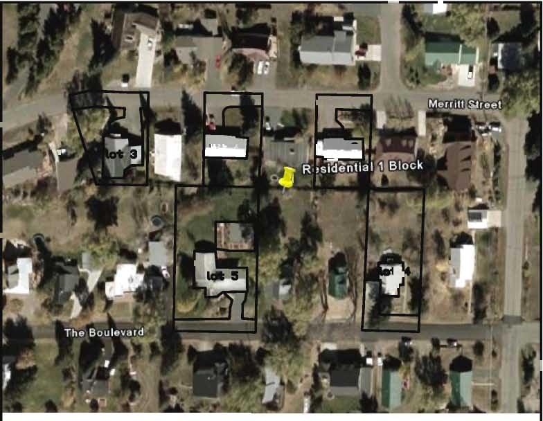
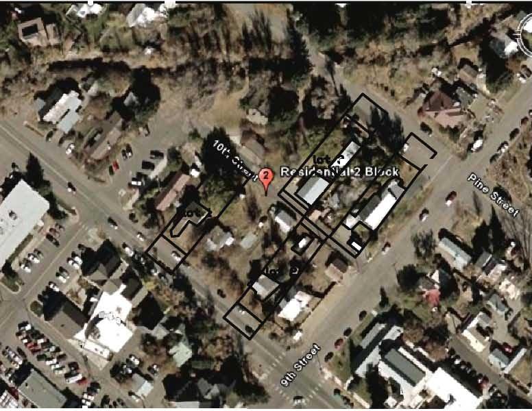
129
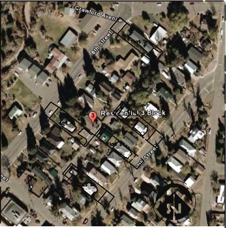

130
131 APPENDIX D: STORM SEWER HYDRAULIC ANALYSIS AND SUPPORTING DOCUMENTATION Old Town Drainage Study and Floodplain Masterplan for Soda, Butcherknife and Spring Creeks

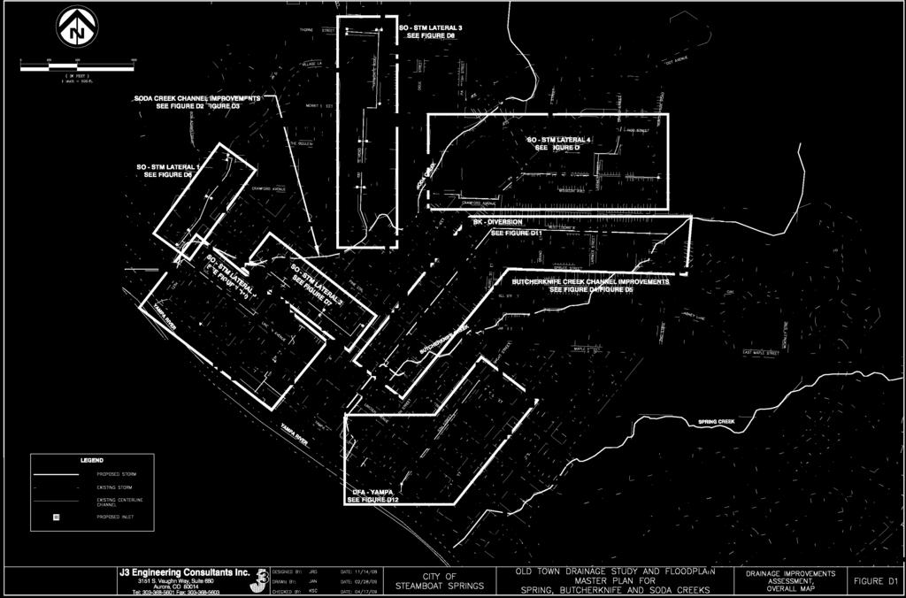
132

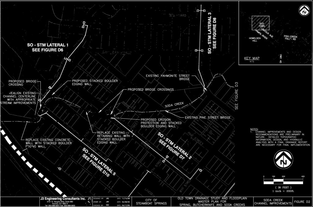
133
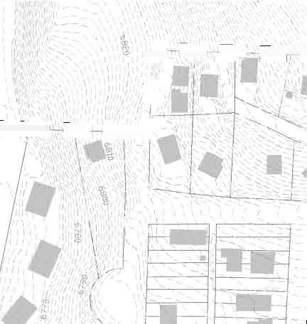
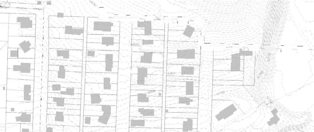
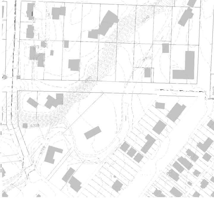
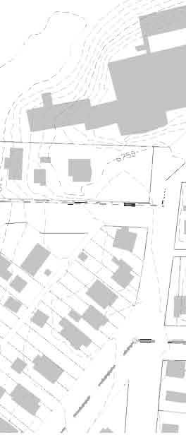
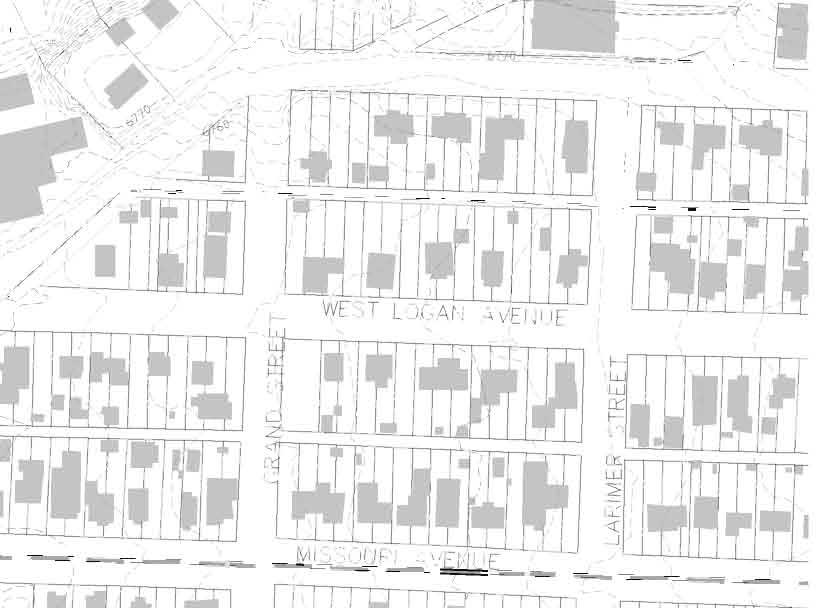
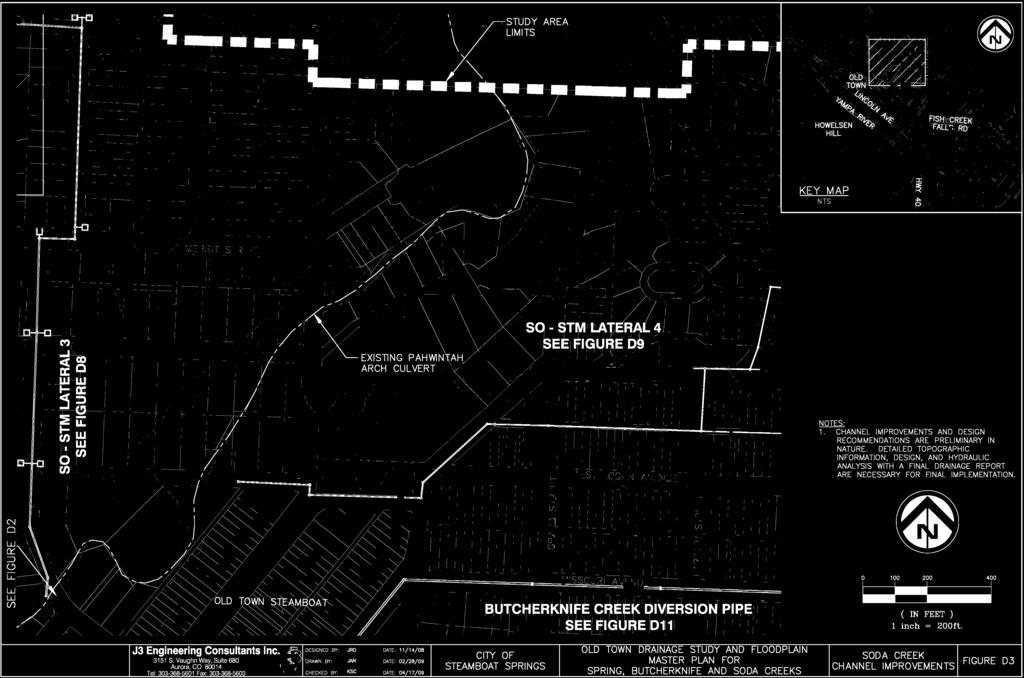
134
135 COMMENTARY FIGURES D2 AND D3 SODA CREEK CHANNEL IMPROVEMENTS DESCRIPTION The Soda Creek channel improvements include stream restoration from the confluence of the Yampa River through Oak Street. The improvements include realigning the channel downstream of Lincoln Avenue for hydraulic efficiency and removing and replacing the existing deteriorated walls adjacent to the Warner Library and park. The improvements also include replacing the existing culvert under Lincoln Avenue with a conceptually sized 32-foot wide bridge crossing. The existing culverts located under 11th and Oak Street are also hydraulically undersized and would be replaced with 32-foot wide culverts or potentially an open-span bridge. Final design and hydraulic analysis of these crossings will ultimately determine the configuration and width of the structures. Ideally, the final design will include improvements to the culvert alignment, channel profile, entrance and exit conditions and channel stability to improve hydraulic performance and to optimize/minimize structure size. The open channel between the 11th Street and Oak Street culverts could likely be designed as one continuous culvert to reduce energy loses th PRELIMINARY DESIGN COST ESTIMATE Improvement Quantity Unit Unit Cost Total Cost Channel Improvements 300 LF $ $120,000 32' (W) Bridge Crossing (Lincoln Avenue) 120 LF $10, $1,200,000 32' (W) Culvert Crossing (11th and Oak Street) 125 LF $7, $937,500 Grouted Boulder Stacked Wall Edge 985 LF $ $123,125 Channel Riprap Outlet Protection (Lincoln Avenue) 1 EA $10, $10,000 Channel Riprap Outlet Protection (11th Street) 1 EA $10, $10,000 Channel Riprap Outlet Protection (Oak Street) 1 EA $20, $20,000 Total Estimated Construction Cost $2,420,625 Utility Relocation (5% of Construction Cost) $121,031 Engineering and Contingency (35% of Construction and Utility) $889,580 TOTAL ESTIMATED COST $3,431,236
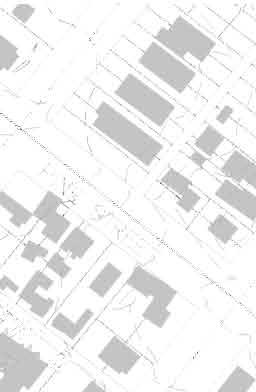


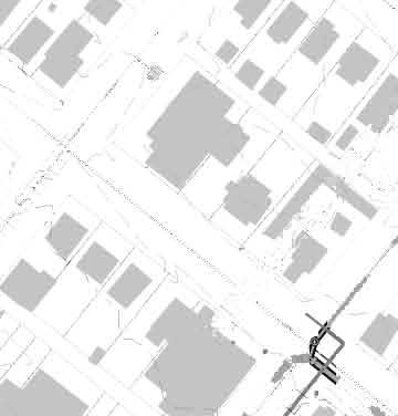

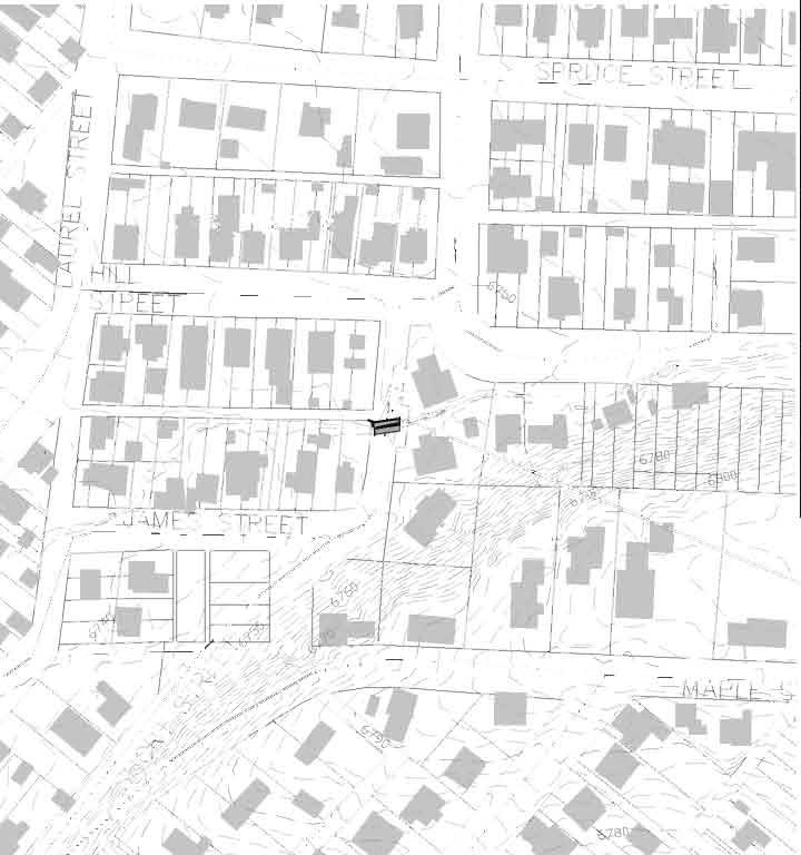

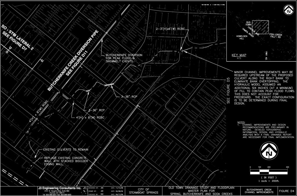
136
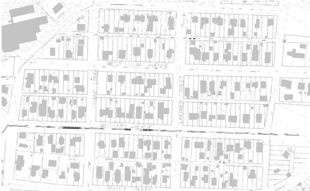
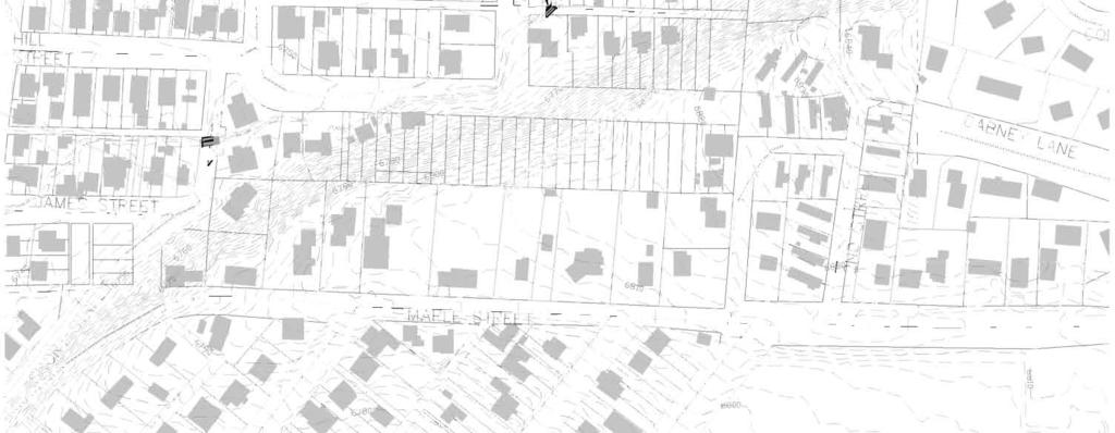
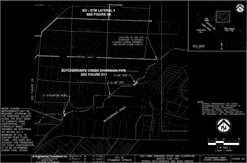
137
138 COMMENTARY FIGURES D4 AND D5 BUTCHERKNIFE CREEK CHANNEL IMPROVEMENTS DESCRIPTION The Butcherknife Creek channel improvements includes the segment of stream from the diversion located at Stehley Park to the confluence with the Yampa River. The 100-year storm event documented in the 2005 FIS estimates the peak flow to be 325 cfs through the City of Steamboat Springs. The preliminary design and associated cost estimate assumes construction of the diversion pipe, which reduces the main channel flow by approximately 200 cfs. The costs associated with the diversion pipe are estimated in the commentary in Figure D11 and are not included with this sheet. Downstream of Oak Street, Butcherknife Creek is conveyed within a 4' (H) by 8' (W) RCBC. Upstream of Oak Street, the existing channel crossings are hydraulically inadequate and require improvements. Crossings under the alley between Oak Street and Pine Street, Pine Street, Butcherknife Alley and Spruce Street are estimated to comprise of 3-36" RCP. Due to limited head available and the channel not being able to convey the flow, the crossing under Short Street should comprise of 2-3' (H) by 6' (W) RCBC and some upstream channel improvements to increase hydraulic efficiency. PRELIMINARY DESIGN COST ESTIMATE Improvement Quantity Unit Unit Cost Total Cost 4' (H) by 8' (W) RCBC 795 LF $ $576,375 3' (H) by 6' (W) RCBC 70 LF $ $33,250 Precast 4' (H) by 8' (W) RCBC 22.5 Bends 11 EA $2, $27,500 36" RCP 630 LF $ $91,350 Grouted Boulder Stacked Wall Edge 80 FF $ $10,000 Channel Riprap Outfall Protection 7 EA $10, $70,000 Channel Improvements 150 LF $ $60,000 Note: 157 LF of this is currently designed and planned for construciton as part of a CDOT US-40 Highway Improvement Project. These costs are currently being refined as part of a cost sharing agreement between the City of Steamboat Springs and CDOT and so that quantity is within this estimate. Total Estimated Construction Cost $868,475 Utility Relocation (5% of Construction Cost) $43,424 Engineering and Contingency (35% of Construction and Utility) $319,165 TOTAL ESTIMATED COST $1,231,063


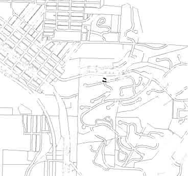


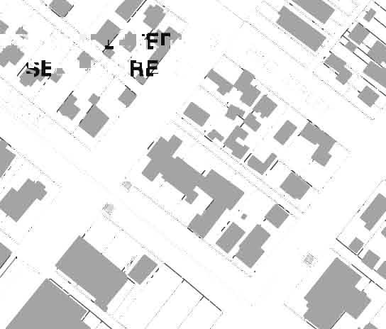
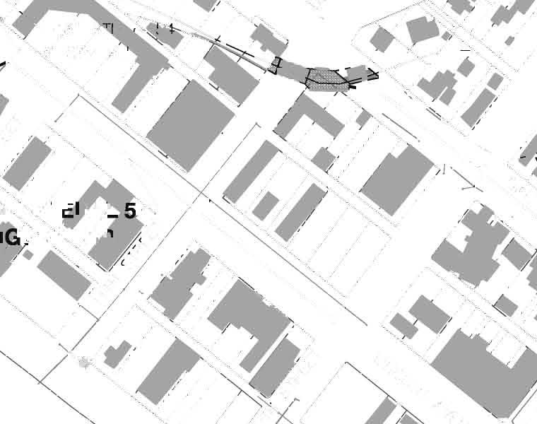
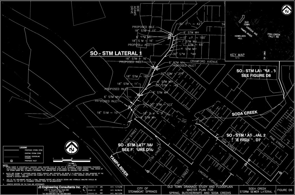
139
140 COMMENTARY FIGURE D6 SO - STM LATERAL 1 DESCRIPTION Street capacity is exceeded at the intersection of Bob Adams Drive and The Boulevard at Design Point SO-C3. Therefore, the storm sewer was extended to that intersection location for the necessary inlets. Inlets were added along the storm sewer lateral to capture additional surface flow to take advantage of the proposed storm sewer. Final design will need to determine final location of inlets and storm sewer and the number of inlets. SO - Storm Lateral 1 will discharge into Soda Creek upstream of the bridge / culvert located at Lincoln Avenue. PRELIMINARY DESIGN COST ESTIMATE Improvement Quantity Unit Unit Cost Total Cost 18" CMP 140 LF $60.00 $8,400 30" CMP 935 LF $ $102,850 Inlets 6 EA $5, $30,000 Manhole, 6' Diameter 2 EA $3, $6,800 Manhole, 5' Diameter 6 EA $2, $15,000 Manhole, 4' Diameter 1 EA $2, $2,150 Riprap Outlet Protection 1 EA $2, $2,000 Connection to Existing Infrastructure EA $3, $0 Total Estimated Construction Cost $167,200 Utility Relocation (5% of Construction Cost) $8,360 Engineering and Contingency (35% of Construction and Utility) $61,446 TOTAL ESTIMATED COST $237,006
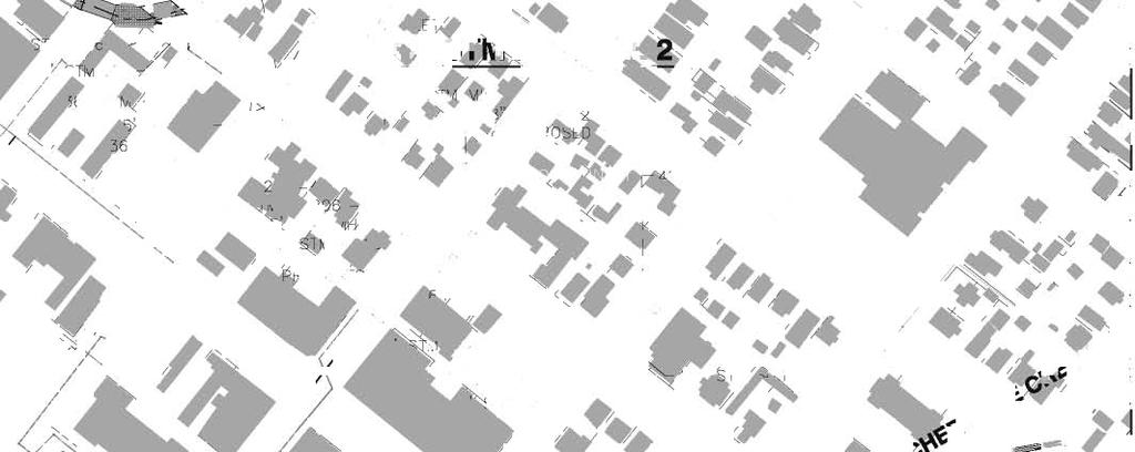
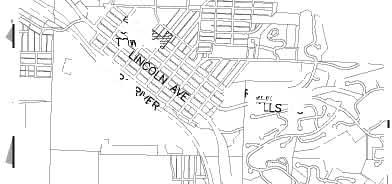
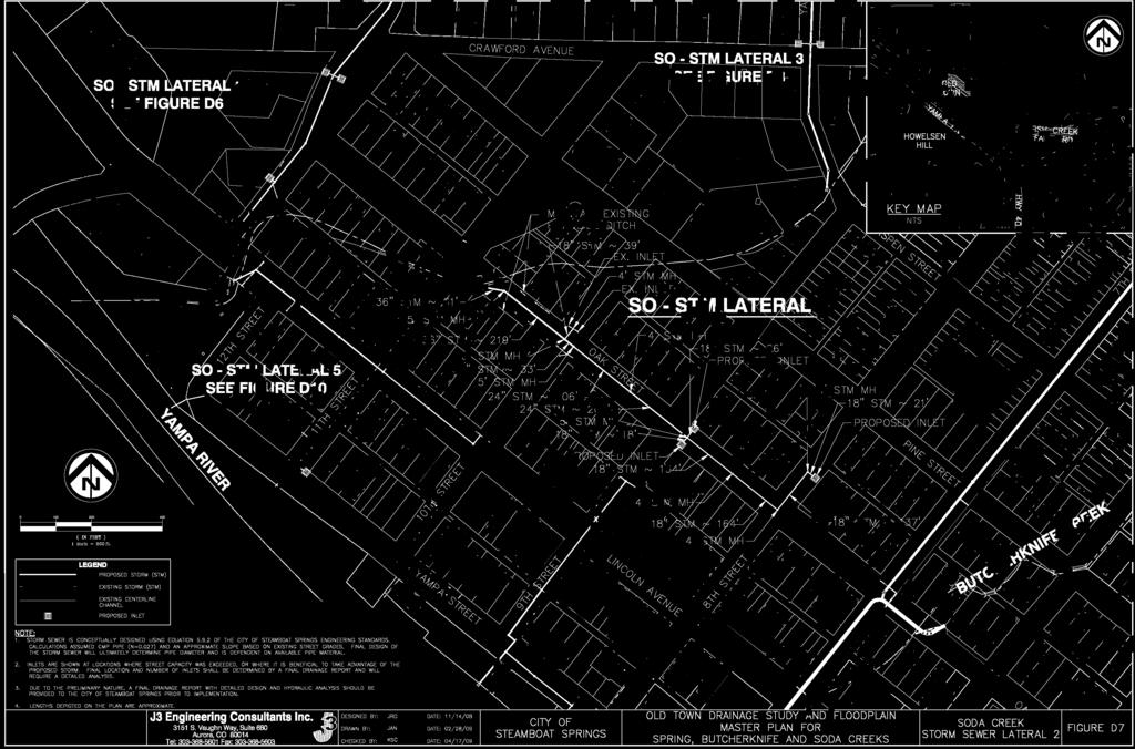
141
142 COMMENTARY FIGURE D7 SO - STM LATERAL 2 DESCRIPTION Street capacity for the minor storm event is exceeded for the tributary area along Oak Street. SO - Lateral 2 extends from Soda Creek to 8th Street. The lateral was extended northeast along 8th Street to a proposed inlet near the church to capture and convey the surface discharge from a sump pump. Groundwater causes a nuisance surface flow that begins at this location and persisted along Oak Street to Soda Creek. Several existing inlets and roadside ditches are present along Oak Street. The existing inlets will be connected to the proposed line and it is recommended that the roadside ditches remain in place to convey snowmelt runoff and portions of the 100-year storm event. Final design will need to determine final location of inlets and storm sewer and the number of inlets. PRELIMINARY DESIGN COST ESTIMATE Improvement Quantity Unit Unit Cost Total Cost 36" CMP 315 LF $ $40,950 24" CMP 410 LF $88.00 $36,080 18" CMP 595 EA $60.00 $35,700 Inlets 3 EA $5, $15,000 Manhole, 5' Diameter 4 EA $2, $10,000 Manhole, 4' Diameter 5 EA $2, $10,750 Riprap Outlet Protection 1 EA $2, $2,000 Connection to Existing Infrastructure 2 EA $3, $6,000 Head Wall, Pipe Penetration 1 EA $5, $5,000 Total Estimated Construction Cost $161,480 Utility Relocation (5% of Construction Cost) $8,074 Engineering and Contingency (35% of Construction and Utility) $59,344 TOTAL ESTIMATED COST $228,898


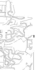
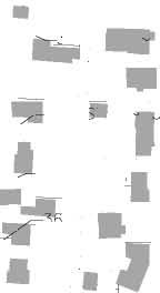

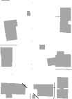
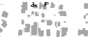


143
144 COMMENTARY FIGURE D8 SO - STM LATERAL 3 DESCRIPTION Street capacity is exceeded higher in this basin at the intersection of Thornberg Street and Uncochief Street at Design Point SO-B3. Therefore, storm sewer was extended to the location for necessary inlets. Several areas along Yahmonite Road were identified as problematic with localized flooding and nuisance flows. As a result, inlets were added along the storm sewer lateral to capture additional surface flow and help minimize the problematic nuisance flows. The existing roadside ditches are recommended to remain in place to convey the 100-year storm event. SO - Storm Lateral 3 will discharge into Soda Creek directly downstream of Yahmonite Bridge. Final design will need to determine final location of inlets and storm sewer and the number of inlets. PRELIMINARY DESIGN COST ESTIMATE Improvement Quantity Unit Unit Cost Total Cost 42" RCP 1,120 LF $ $179,200 36" CMP 1,050 LF $ $136,500 18" CMP 225 EA $60.00 $13,500 Inlets 10 EA $5, $50,000 Manhole, 7' Diameter 3 EA $5, $15,000 Manhole, 6' Diameter 5 EA $3, $17,000 Manhole, 5' Diameter 3 EA $2, $7,500 Manhole, 4' Diameter 1 EA $2, $2,150 Riprap Outfall Protection 1 EA $2, $2,000 42" FES 1 EA $3, $3,000 Total Estimated Construction Cost $246,650 Utility Relocation (5% of Construction Cost) $12,333 Engineering and Contingency (35% of Construction and Utility) $90,644 TOTAL ESTIMATED COST $349,626

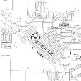


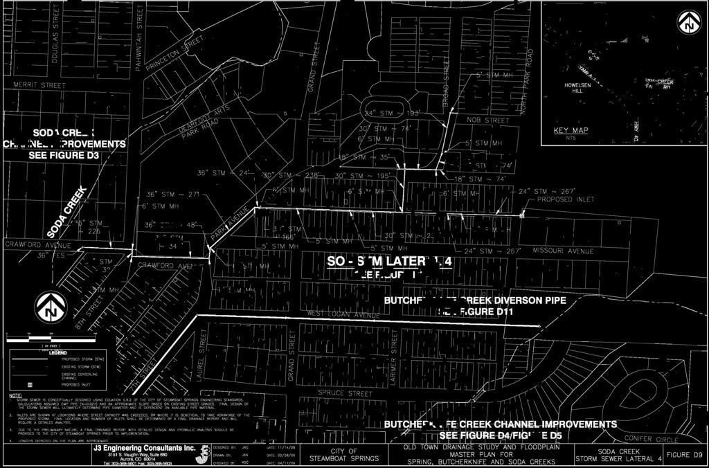
145
146 COMMENTARY FIGURE D9 SO - STM LATERAL 4 DESCRIPTION Street capacity is exceeded at Design Point SO-F1, which is located at the intersection of Broad Street and Nob Street. Existing inlets are present at this location and an existing storm sewer lateral conveys flow past the school to Soda Creek. Pipe diameter and conditions of the existing infrastructure in the upper portions of the basin are unknown. Sizes of the existing storm sewer infrastructure adjacent to the recently redeveloped school were provided based on the design report. The recently installed storm sewer main that conveys flow to Soda Creek adjacent to the school is undersized for conveyance of the entire watershed. Therefore, SO - Storm Lateral 4 recommends upsizing the main conveyance line from Soda Creek to the intersection of Broad Street and Nob Street. Existing inlets and the infrastructure conveying flows will have to be evaluated at final design and may be adequate to convey runoff to the proposed main lateral. Final design will need to determine final location of inlets and storm sewer and the number of inlets. PRELIMINARY DESIGN COST ESTIMATE Improvement Quantity Unit Unit Cost Total Cost 36" CMP 1,585 LF $ $206,050 30" CMP 335 LF $ $36,850 24" CMP 830 LF $88.00 $73,040 18" CMP 65 EA $60.00 $3,900 Inlets 1 EA $5, $5,000 Manhole, 7' Diameter 2 EA $5, $10,000 Manhole, 6' Diameter 6 EA $3, $20,400 Manhole, 5' Diameter 6 EA $2, $15,000 Riprap Outlet Protection 1 EA $2, $2,000 Connection to Existing Infrastructure 11 EA $3, $33,000 36" FES 1 EA $1, $1,115 Total Estimated Construction Cost $406,355 Utility Relocation (5% of Construction Cost) $20,318 Engineering and Contingency (35% of Construction and Utility) $149,335 TOTAL ESTIMATED COST $576,008

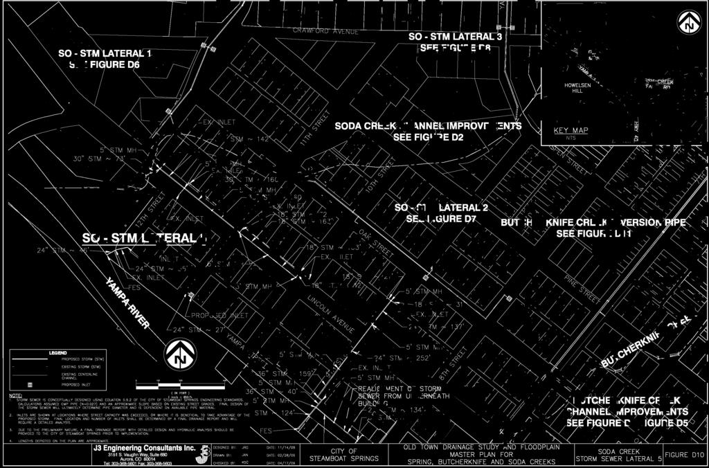
147
148 COMMENTARY FIGURE D10 SO - STM LATERAL 5 DESCRIPTION SO - Storm Lateral 5 comprises of the storm sewer alignment along Lincoln Avenue. An existing storm line conveys flow but is inadequate for the design storm and required upsizing. The outfall of Storm Lateral 5 into Soda Creek is downstream of the bridge/culvert crossing under Lincoln Avenue. In addition to the main Storm Lateral 5, minor storm infrastructure improvements are also shown within Figure D10. These improvements comprise of increasing the storm sewer at the intersection of 12th Street and Yampa Street, adding an inlet for local nuisance drainage at the southeast corner of the intersection of 11th Street and Yampa Street, realigning the outfall under the Steamboat Yacht Club and combining and upsizing the storm outfall along 9th Street, and increasing size of the existing storm sewer along 9th Avenue between Lincoln Avenue and the alley to the northeast. Final design will need to determine final location of inlets and storm sewer and the number of inlets. PRELIMINARY DESIGN COST ESTIMATE Improvement Quantity Unit Unit Cost Total Cost 30" CMP 880 LF $ $96,800 24" CMP 780 LF $88.00 $68,640 18" CMP 430 EA $60.00 $25,800 Manhole, 5' Diameter 13 EA $2, $32,500 Riprap Outfall Protection 4 EA $2, $8,000 Connection to Existing Infrastructure 15 EA $3, $45,000 Head Wall, Pipe Penetration 1 EA $5, $5,000 24" FES 1 EA $ $975 30" FES 1 EA $1, $1,050 Total Estimated Construction Cost $283,765 Utility Relocation (5% of Construction Cost) $14,188 Engineering and Contingency (35% of Construction and Utility) $104,284 TOTAL ESTIMATED COST $402,237


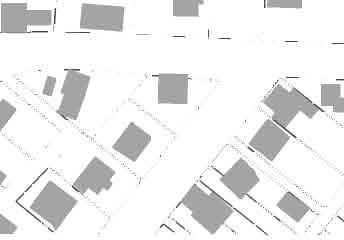


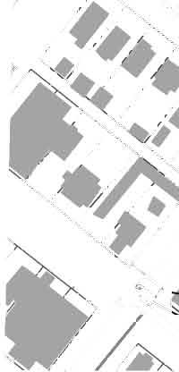

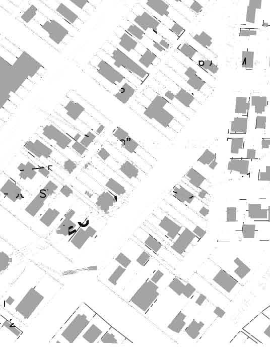
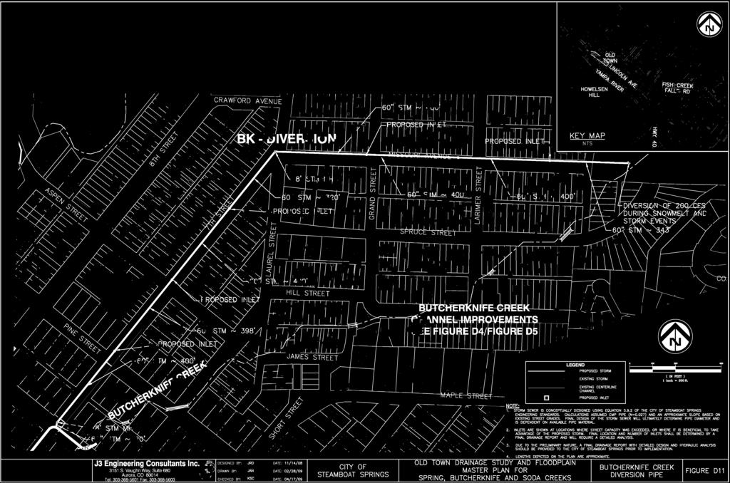
149
150 COMMENTARY FIGURE D11 BUTCHERKNIFE CREEK DIVERSION DESCRIPTION To reduce the 100-year flows in Butcherknife Creek, an in-channel diversion structure and diversion pipe are proposed. The Butcherknife Creek Diversion Pipe is modeled and priced as a 60" RCP. The improvements will reduce the peak storm event and snowmelt runoff within the main channel of Butcherknife Creek. The main channel of Butcherknife Creek has limited flow capacity so the overflow pipe helps to minimize nuisance flooding along the channel corridor and flooding caused by storm events. The 60" diversion pipe was conceptually designed to convey approximately 200 cfs and is aligned along Missouri Avenue to 7th Street. Near the intersection of 7th Street and Oak Street, the diversion would connect to the 4-foot high by 8-foot wide reinforced concrete box culvert discussed in commentary Figure D4 for the recombined full flow along Butcherknife Creek. PRELIMINARY DESIGN COST ESTIMATE Improvement Quantity Unit Unit Cost Total Cost 60" RCP 3,085 LF $ $678,700 18" CMP 55 LF $60.00 $3,300 Manhole, Box Base 8 EA $10, $80,000 Connect to Existing Infrastructure 2 EA $3, $6,000 Diversion Structure 1 EA $50, $50,000 The City specifies CMP, but due to the large diameter of this diversion pipe, it may be necessary to select a pipe material with improved hydraulic performance. A price competitive alternative may include steel reinforced HDPE, which combines many of the distinct benefits found individually with RCP and CMP. The price of the diversion structure may vary greatly depending on the how sophisticated the City wishes the structure to be. It is possible to incorporate telemetry, SCADA, and/or automatic controls that regulate the peak flow within Butcherknife Creek. For this reason, a middle of the road unit cost was selected. The diversion pipe also provides conveyance for some local drainage along 7th Avenue. Final design will need to determine final location of inlets and storm sewer and the number of inlets. Total Estimated Construction Cost $818,000 Utility Relocation (5% of Construction Cost) $40,900 Engineering and Contingency (35% of Construction and Utility) $300,615 TOTAL ESTIMATED COST $1,159,515


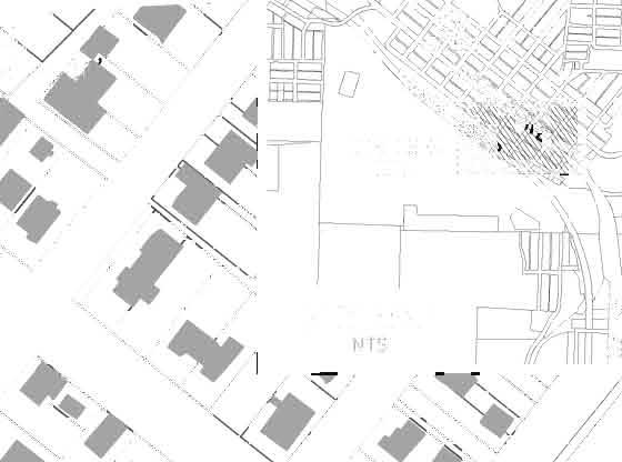


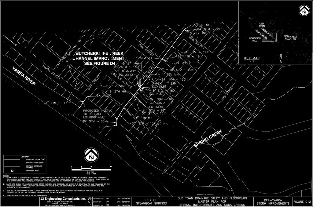
151
152 COMMENTARY FIGURE D12 DFA - Yampa Storm Improvements DESCRIPTION DFA Yampa Storm Improvements include the lateral improvements along 5th Street and 6th Street. The lateral line along 5th Street needs to improved to provide additional drainage conveyance capacity between the outfall at the Yampa River to Lincoln Avenue. Along 6th Avenue the storm sewer from the outfall at the Yampa River to the inlet on the upstream side (northeast) of Yampa Street. Final design will need to determine final location of inlets and storm sewer and the number of inlets. PRELIMINARY DESIGN COST ESTIMATE Improvement Quantity Unit Unit Cost Total Cost 36" CMP 65 LF $ $8,450 30" CMP 390 LF $ $42,900 24" CMP 935 LF $88.00 $82,280 18" CMP 65 LF $60.00 $3,900 Manhole, 6' Diameter 2 EA $3, $6,800 Manhole, 5' Diameter 5 EA $2, $12,500 Riprap Outfall Protection 2 EA $2, $4,000 Connection to Existing Infrastructure 6 EA $3, $18,000 24" FES 1 EA $ $975 36" FES 1 EA $1, $1,115 Total Estimated Construction Cost $180,920 Utility Relocation (5% of Construction Cost) $9,046 Engineering and Contingency (35% of Construction and Utility) $66,488 TOTAL ESTIMATED COST $256,454
153 STORM SEWER DESIGN Soda Creek Job No. Date Calculated By Checked By /16/2009 JRD KSC DESIGN EQUATION: Intial storm sewer size and design is based on Equation of the Steamboat Springs Engineering Standards. It states: ASSUMPTIONS: D i 2.16nQ =. 1 2 So p 3 8 Where: n = Manning's Roughness Coefficient Q = Peak Discharge (cfs) S = Slope (ft/ft) 1. Corrugated Metal Pipe will be utilized for storm conveyance (n = 0.027) 2. Slope of the storm sewer is approximated by the controlling roadway slope (i.e. the mildest slope) 3. Storm sewer designed for minor storm event (5-year) 4. Due to the conceptual nature of the study, a factor of safety was added DESIGN: Mannings n Factor of Safety 10% Design Point Design Discharge (cfs) Estimated Slope of Pipe (ft/ft) Initial Pipe Diameter (ft) Applying Factor of Safety Selected Pipe Diameter (ft) B B B B B B C C C F F F F F F G G H H H COMMENTS: 1. Due to the conceptual nature of the pipe calculations, a final design report should required and include detail information such as hydraulic design, plan and profiles, etc.
154 STORM SEWER DESIGN Direct Flow Area - Yampa River Job No. Date Calculated By Checked By /16/2009 JRD KSC DESIGN EQUATION: Intial storm sewer size and design is based on Equation of the Steamboat Springs Engineering Standards. It states: ASSUMPTIONS: D i 2.16nQ =. 1 2 So p 3 8 Where: n = Manning's Roughness Coefficient Q = Peak Discharge (cfs) S = Slope (ft/ft) 1. Corrugated Metal Pipe will be utilized for storm conveyance (n = 0.027) 2. Slope of the storm sewer is approximated by the controlling roadway slope (i.e. the mildest slope) 3. Storm sewer designed for minor storm event (5-year) 4. Due to the conceptual nature of the study, a factor of safety was added DESIGN: Mannings n Factor of Safety 10% Design Point Design Discharge (cfs) Estimated Slope of Pipe (ft/ft) Initial Pipe Diameter (ft) Applying Factor of Safety Selected Pipe Diameter (ft) Y Y Y Y Y Y Y Y Y Y Y Y Y Y Y Y Y Y
155 STORM SEWER DESIGN Direct Flow Area - Yampa River Job No. Date Calculated By Checked By /16/2009 JRD KSC DESIGN EQUATION: Intial storm sewer size and design is based on Equation of the Steamboat Springs Engineering Standards. It states: ASSUMPTIONS: D i 2.16nQ =. 1 2 So p 3 8 Where: n = Manning's Roughness Coefficient Q = Peak Discharge (cfs) S = Slope (ft/ft) 1. Corrugated Metal Pipe will be utilized for storm conveyance (n = 0.027) 2. Slope of the storm sewer is approximated by the controlling roadway slope (i.e. the mildest slope) 3. Storm sewer designed for minor storm event (5-year) 4. Due to the conceptual nature of the study, a factor of safety was added DESIGN: Mannings n Factor of Safety 10% Design Point Design Discharge (cfs) Estimated Slope of Pipe (ft/ft) Initial Pipe Diameter (ft) Applying Factor of Safety Selected Pipe Diameter (ft) Y23a Y Y Y Y Y Y Y Y COMMENTS: 1. Due to the conceptual nature of the pipe calculations, a final design report should required and include detail information such as hydraulic design, plan and profiles, etc.
156 APPENDIX E: HEC-RAS OUTPUT Old Town Drainage Study and Floodplain Masterplan for Soda, Butcherknife and Spring Creeks


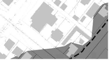

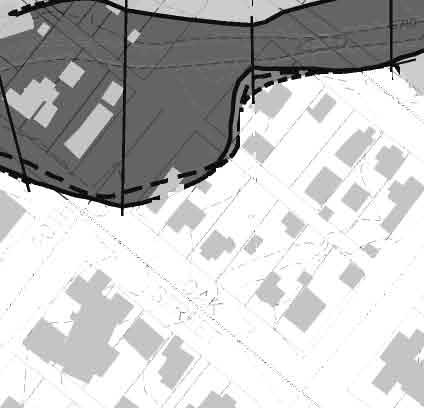
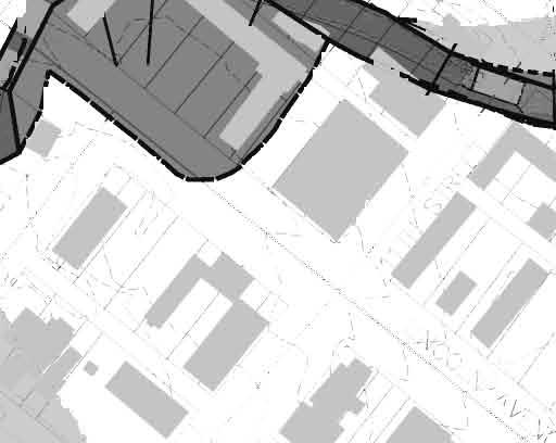

157
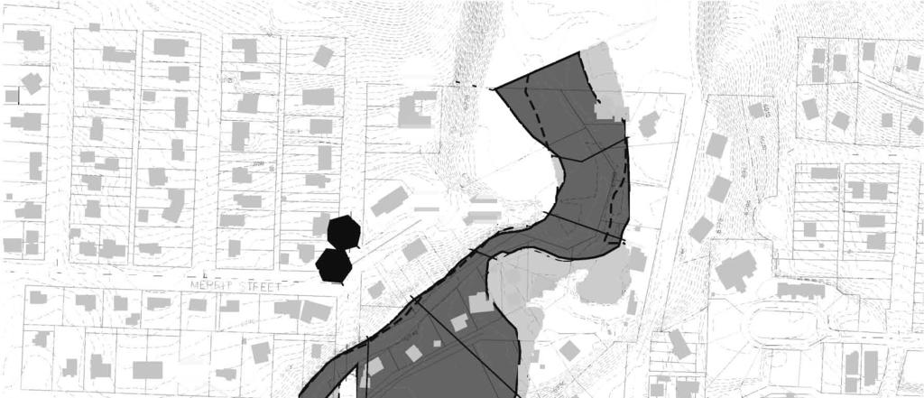
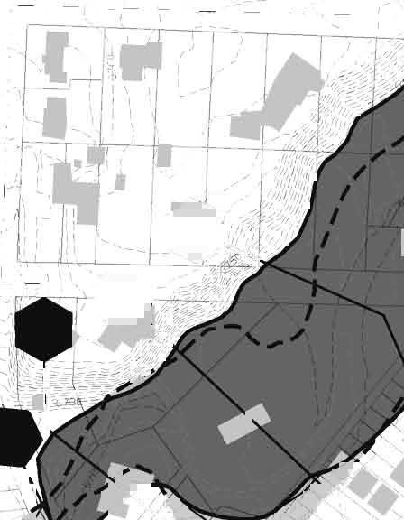
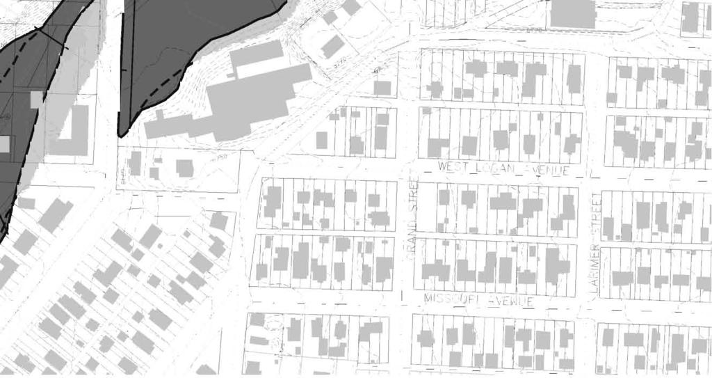
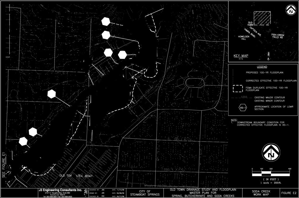
158


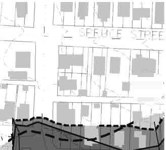
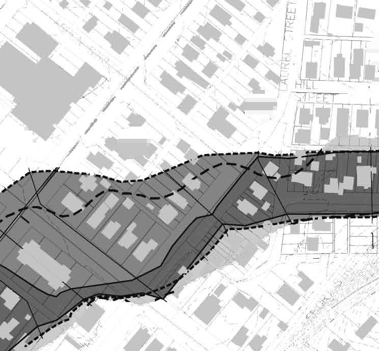

159
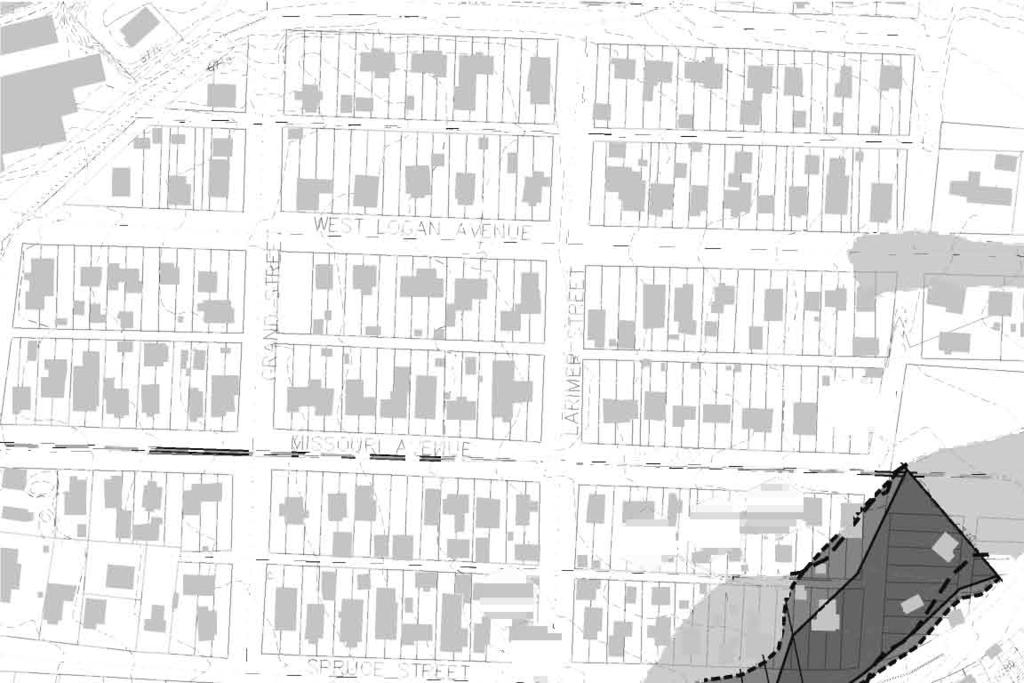
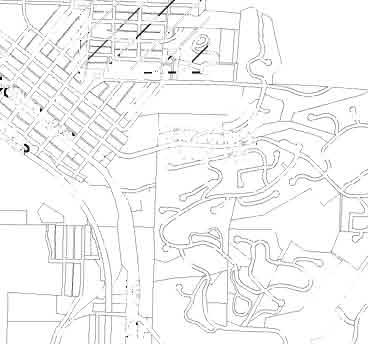
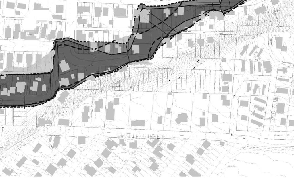
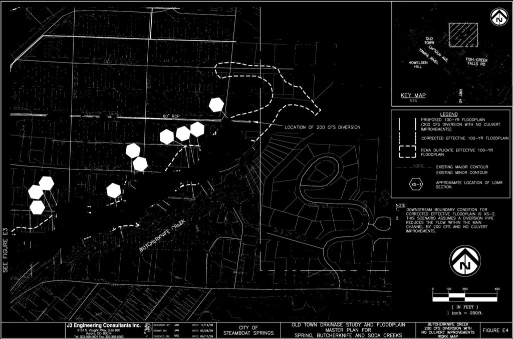
160


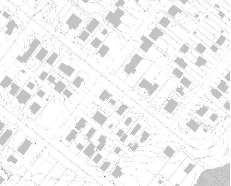
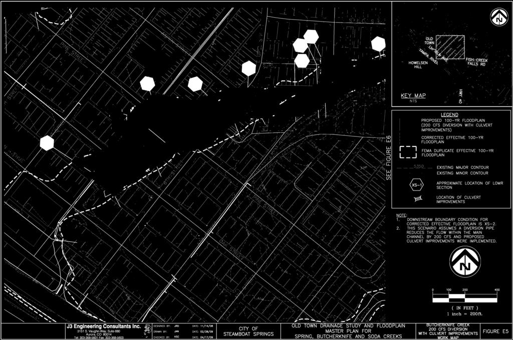
161
Section 4: Model Development and Application
 Section 4: Model Development and Application The hydrologic model for the Wissahickon Act 167 study was built using GIS layers of land use, hydrologic soil groups, terrain and orthophotography. Within
PENNSYLVANIA DEPARTMENT OF TRANSPORTATION ENGINEERING DISTRICT 3-0
 PENNSYLVANIA DEPARTMENT OF TRANSPORTATION ENGINEERING DISTRICT 3-0 LYCOMING COUNTY S.R.15, SECTION C41 FINAL HYDROLOGIC AND HYDRAULIC REPORT STEAM VALLEY RUN STREAM RELOCATION DATE: June, 2006 REVISED:
YELLOWSTONE RIVER FLOOD STUDY REPORT TEXT
 YELLOWSTONE RIVER FLOOD STUDY REPORT TEXT TECHNICAL REPORT Prepared for: City of Livingston 411 East Callender Livingston, MT 59047 Prepared by: Clear Creek Hydrology, Inc. 1627 West Main Street, #294
Chapter 7 Mudflow Analysis
 Chapter 7 Mudflow Analysis 7.0 Introduction This chapter provides information on the potential and magnitude of mud floods and mudflows that may develop in Aspen due to rainfall events, snowmelt, or rain
UPPER COSUMNES RIVER FLOOD MAPPING
 UPPER COSUMNES RIVER FLOOD MAPPING DRAFT BASIC DATA NARRATIVE FLOOD INSURANCE STUDY SACRAMENTO COUTY, CALIFORNIA Community No. 060262 November 2008 Prepared By: CIVIL ENGINEERING SOLUTIONS, INC. 1325 Howe
Chapter 7 Mudflow Analysis
 Chapter 7 Mudflow Analysis 7.0 Introduction This chapter provides information on the potential and magnitude of mud floods and mudflows that may develop in Aspen due to rainfall events, snowmelt, or rain
City of Thornton Attn: Tim Semones Development Engineeering 9500 Civic Center Dr. Thornton, CO 80229
 Development Engineering Land Surveying Construction Administration District Services October 20, 2017 City of Thornton Attn: Tim Semones Development Engineeering 9500 Civic Center Dr. Thornton, CO 80229
LOMR SUBMITTAL LOWER NEHALEM RIVER TILLAMOOK COUNTY, OREGON
 LOMR SUBMITTAL LOWER NEHALEM RIVER TILLAMOOK COUNTY, OREGON Prepared for: TILLAMOOK COUNTY DEPARTMENT OF COMMUNITY DEVELOPMENT 1510-B THIRD STREET TILLAMOOK, OR 97141 Prepared by: 10300 SW GREENBURG ROAD,
Pequabuck River Flooding Study and Flood Mitigation Plan The City of Bristol and Towns of Plainville and Plymouth, CT
 Pequabuck River Flooding Study and Flood Mitigation Plan The City of Bristol and Towns of Plainville and Plymouth, CT Raymond Rogozinski and Maged Aboelata The City of Bristol and Towns of Plainville and
CASE STUDIES. Introduction
 Introduction The City of Winston-Salem faces the challenge of maintaining public infrastructure (e.g., water and sewer lines, storm drains, roads, culverts and bridges) while minimizing the potential impacts
Hydrology and Hydraulics Design Report. Background Summary
 To: National Park Services Montezuma Castle National Monument Richard Goepfrich, Facility Manager From: Multicultural Technical Engineers Date: Tuesday - February 13, 2018 Subject: 30% Hydrology and Hydraulics
The last three sections of the main body of this report consist of:
 Threatened and Endangered Species Geological Hazards Floodplains Cultural Resources Hazardous Materials A Cost Analysis section that provides comparative conceptual-level costs follows the Environmental
LOMR SUBMITTAL LOWER NESTUCCA RIVER TILLAMOOK COUNTY, OREGON
 LOMR SUBMITTAL LOWER NESTUCCA RIVER TILLAMOOK COUNTY, OREGON Prepared for: TILLAMOOK COUNTY DEPARTMENT OF COMMUNITY DEVELOPMENT 1510-B THIRD STREET TILLAMOOK, OR 97141 Prepared by: 10300 SW GREENBURG ROAD,
STREUVER FIDELCO CAPPELLI, LLC YONKERS DOWNTOWN DEVELOPMENT PHASE 1. DRAFT ENVIRONMENTAL IMPACT STATEMENT For: PALISADES POINT
 STREUVER FIDELCO CAPPELLI, LLC YONKERS DOWNTOWN DEVELOPMENT PHASE 1 DRAFT ENVIRONMENTAL IMPACT STATEMENT For: PALISADES POINT Prepared by: PAULUS, SOKOLOWSKI & SARTOR STORMWATER MANAGEMENT 1. Methodology
LOCATED IN INDIAN RIVER COUNTY PREPARED FOR S.J.R.W.M.D. AND F.W.C.D. DECEMBER, 2003 Updated 2007 Updated May 2014 PREPARED BY
 FELLSMERE WATER CONTROL DISTRICT EAST MASTER DRAINAGE PLAN AND STORMWATER HYDROLOGIC ANALYSIS OF THE GRAVITY DRAINAGE SYSTEM LOCATED BETWEEN THE EAST BOUNDARY, LATERAL U, THE MAIN CANAL, AND DITCH 24 LOCATED
Appendix E Guidance for Shallow Flooding Analyses and Mapping
 Appendix E Guidance for Shallow Flooding Analyses and Mapping E.1 Introduction Different types of shallow flooding commonly occur throughout the United States. Types of flows that result in shallow flooding
Appendix C Fluvial Flood Hazards
 Appendix C Fluvial Flood Hazards Sea Level Rise Vulnerability Assessment and Adaptation Project March 2019 Contents Contents... i Figures... i Tables... i Definitions, Acronyms, & Abbreviations... ii
3.11 Floodplains Existing Conditions
 Other stormwater control practices may be needed to mitigate water quality impacts. In addition to detention facilities, other practices such as vegetated basins/buffers, infiltration basins, and bioswales
3301 East 120 th Avenue Assited Living & Memory Care
 UTILITY REPORT FOR 3301 East 120 th Avenue Assited Living & Memory Care 1 st Submittal January 23, 2016 2 nd Submittal March 04, 2016 Prepared for: 3301 E. 120 th Ave, LLC. 8200 E. Maplewood Ave., Suite
HISTORY OF CONSTRUCTION FOR EXISTING CCR SURFACE IMPOUNDMENT PLANT GASTON ASH POND 40 CFR (c)(1)(i) (xii)
(1)(i) (xii)") HISTORY OF CONSTRUCTION FOR EXISTING CCR SURFACE IMPOUNDMENT PLANT GASTON ASH POND 40 CFR 257.73(c)(1)(i) (xii) (i) Site Name and Ownership Information: Site Name: E.C. Gaston Steam Plant Site Location:
HISTORY OF CONSTRUCTION FOR EXISTING CCR SURFACE IMPOUNDMENT PLANT GASTON ASH POND 40 CFR 257.73(c)(1)(i) (xii) (i) Site Name and Ownership Information: Site Name: E.C. Gaston Steam Plant Site Location:
Gully Erosion Part 1 GULLY EROSION AND ITS CAUSES. Introduction. The mechanics of gully erosion
 Gully Erosion Part 1 GULLY EROSION AND ITS CAUSES Gully erosion A complex of processes whereby the removal of soil is characterised by incised channels in the landscape. NSW Soil Conservation Service,
CITY OF CAPE CORAL STORMWATER MASTER PLAN PHASE II - PART 1 BASINS 4, 10, & 14 SUB-BASIN DRAINAGE IMPROVEMENTS HYDRAULIC ANALYSIS SUMMARY
 CITY OF CAPE CORAL STORMWATER MASTER PLAN PHASE II - PART 1 BASINS 4, 10, & 14 SUB-BASIN DRAINAGE IMPROVEMENTS HYDRAULIC ANALYSIS SUMMARY Cape Coral, FL Prepared for: The City of Cape Coral Public Works
Ground Water Protection Council 2017 Annual Forum Boston, Massachusetts. Ben Binder (303)
") Ground Water Protection Council 2017 Annual Forum Boston, Massachusetts Protecting Groundwater Sources from Flood Borne Contamination Ben Binder (303) 860-0600 Digital Design Group, Inc. The Problem Houston
Ground Water Protection Council 2017 Annual Forum Boston, Massachusetts Protecting Groundwater Sources from Flood Borne Contamination Ben Binder (303) 860-0600 Digital Design Group, Inc. The Problem Houston
Dealing with Zone A Flood Zones. Topics of Discussion. What is a Zone A Floodplain?
 Dealing with Zone A Flood Zones Topics of Discussion Overview of Zone A Floodplains Permitting Development in Zone A Floodplains Estimating Flood Elevations in Zone A Flood Insurance Implications Letters
BRANDON LAKES AVENUE PRE AND POST CONDITIONS DRAINAGE REPORT
 BRANDON LAKES AVENUE PRE AND POST CONDITIONS DRAINAGE REPORT Hillsborough County Public Works County Center, 22nd Floor 601 E. Kennedy Blvd. Tampa, FL 33602 BRANDON LAKES AVENUE DRAINAGE IMPROVEMENTS Capital
Hydrology Study Report
 Hafeez Consulting www.hafeezconsulting.com Civil/ Structural Engineering, Design & Construction 1451 S. Hacienda St. Anaheim CA 92804 (714) 225-4565 Fax (714)917-2977 engineer@hafeezconsulting.com Hydrology
PRELIMINARY CULVERT ANALYSIS REPORT FOR CULVERT NO. 008-C OREGON AVENUE OVER PINEHURST CREEK
 PRELIMINARY CULVERT ANALYSIS REPORT FOR CULVERT NO. 008-C OREGON AVENUE OVER PINEHURST CREEK Prepared for The District of Columbia Department of Transportation Washington, D.C. Prepared by Parsons Transportation
FHWA - HIGHWAY HYDROLOGY
 The unit peak discharge is computed with Equation 5.6 by interpolating c 0, c, and c Table 5.5 using a type II distribution. The peak discharge is also calculated as follows. from Variable SI Unit U Unit.5444
INFLOW DESIGN FLOOD CONTROL SYSTEM PLAN 40 C.F.R. PART PLANT YATES ASH POND 2 (AP-2) GEORGIA POWER COMPANY
 GEORGIA POWER COMPANY") INFLOW DESIGN FLOOD CONTROL SYSTEM PLAN 40 C.F.R. PART 257.82 PLANT YATES ASH POND 2 (AP-2) GEORGIA POWER COMPANY EPA s Disposal of Coal Combustion Residuals from Electric Utilities Final Rule (40 C.F.R.
INFLOW DESIGN FLOOD CONTROL SYSTEM PLAN 40 C.F.R. PART 257.82 PLANT YATES ASH POND 2 (AP-2) GEORGIA POWER COMPANY EPA s Disposal of Coal Combustion Residuals from Electric Utilities Final Rule (40 C.F.R.
Stormwater Guidelines and Case Studies. CAHILL ASSOCIATES Environmental Consultants West Chester, PA (610)
") Stormwater Guidelines and Case Studies CAHILL ASSOCIATES Environmental Consultants West Chester, PA (610) 696-4150 www.thcahill.com Goals and Challenges for Manual State Stormwater Policy More Widespread
Stormwater Guidelines and Case Studies CAHILL ASSOCIATES Environmental Consultants West Chester, PA (610) 696-4150 www.thcahill.com Goals and Challenges for Manual State Stormwater Policy More Widespread
Materials. Use materials meeting the following.
 208.01 Section 208. SOIL EROSION AND SEDIMENTATION CONTROL 208.01 Description. Install and maintain erosion and sedimentation controls to minimize soil erosion and to control sedimentation from affecting
STORMWATER REPORT FRITO LAY SUBDIVISION NO. 3
 STORMWATER REPORT FRITO LAY SUBDIVISION NO. 3 May 2018 STORMWATER REPORT I. Subdivision Data a. The parcel is adjacent to the existing Frito Lay property in Topeka; and the subject plat application encompasses
SAN FRANCISCO DISTRICT INFORMATION REQUESTED FOR VERIFICATION OF CORPS JURISDICTION
 DEPARTMENT OF THE ARMY SAN FRANCISCO DISTRICT, U.S. ARMY CORPS OF ENGINEERS 1455 MARKET STREET SAN FRANCISCO, CALIFORNIA 94103-1398 SAN FRANCISCO DISTRICT INFORMATION REQUESTED FOR VERIFICATION OF CORPS
REDWOOD VALLEY SUBAREA
 Independent Science Review Panel Conceptual Model of Watershed Hydrology, Surface Water and Groundwater Interactions and Stream Ecology for the Russian River Watershed Appendices A-1 APPENDIX A A-2 REDWOOD
Hydrologic Forecast Centre. Manitoba Infrastructure. Winnipeg, Manitoba FEBRUARY FLOOD OUTLOOK REPORT FOR MANITOBA.
 Page 1 of 20 Hydrologic Forecast Centre Manitoba Infrastructure Winnipeg, Manitoba FEBRUARY FLOOD OUTLOOK REPORT FOR MANITOBA February 28, 2019 Overview The February Outlook Report prepared by the Hydrologic
North Carolina Simplified Inundation Maps For Emergency Action Plans December 2010; revised September 2014; revised April 2015
 North Carolina Simplified Inundation Maps For Emergency Action Plans December 2010; revised September 2014; revised April 2015 INTRODUCTION Emergency Action Plans (EAPs) are critical to reducing the risks
Discovery Data Questionnaire
 Region III Discovery Data Questionnaire Thank you for taking the time to complete this Discovery Data questionnaire. It will provide important information to help FEMA better understand flood risk issues
5.2. IDENTIFICATION OF NATURAL HAZARDS OF CONCERN
 5.2. IDENTIFICATION OF NATURAL HAZARDS OF CONCERN To provide a strong foundation for mitigation strategies considered in Sections 6 and 9, County considered a full range of natural hazards that could impact
Stormwater Capacity Analysis for Westover Branch Watershed
 Stormwater Capacity Analysis for Westover Branch Watershed Pimmit Run Little Pimmit Run, Mainstem Stohman's Run Gulf Branch Pimmit Run Tributary Little Pimmit Run, W. Branch Little Pimmit Run, E. Branch
Solutions to Flooding on Pescadero Creek Road
 Hydrology Hydraulics Geomorphology Design Field Services Photo courtesy Half Moon Bay Review Solutions to Flooding on Pescadero Creek Road Prepared for: San Mateo County Resource Conservation District
Local Flood Hazards. Click here for Real-time River Information
 Local Flood Hazards Floods of the White River and Killbuck Creek are caused by runoff from general, and/or intense rainfall. Other areas of flooding concern are from the Boland Ditch and Pittsford Ditch.
Eastlake Assited Living & Memory Care
 UTILITY REPORT FOR Eastlake Assited Living & Memory Care 1 st Submittal January 23, 2016 2 nd Submittal March 04, 2016 June 7, 2016 Final Submittal August 08, 2016 Prepared for: 3301 E. 120 th Ave, LLC.
SAN JACINTO RIVER / BAUTISTA CREEK LEVEE SYSTEM RIVERSIDE COUNTY, CALIFORNIA NLD ID #
 SAN JACINTO RIVER / BAUTISTA CREEK LEVEE SYSTEM RIVERSIDE COUNTY, CALIFORNIA NLD ID # 3805010019 PERIODIC INSPECTION REPORT NO 1 GENERALIZED EXECUTIVE SUMMARY FEBRUARY 2013 FINAL RATING: MINIMALLY ACCEPTABLE
Continuing Education Associated with Maintaining CPESC and CESSWI Certification
 Continuing Education Associated with Maintaining CPESC and CESSWI Certification Module 2: Stormwater Management Principles for Earth Disturbing Activities Sponsors: ODOTs Local Technical Assistance Program
Community Discovery Data Questionnaire
 Region III Community Discovery Data Questionnaire Thank you for taking the time to complete this questionnaire. It will provide important information to help FEMA understand flood risk issues in the Conococheague-Opequon
Hydrologic Forecast Centre Manitoba Infrastructure, Winnipeg, Manitoba. FEBRUARY OUTLOOK REPORT FOR MANITOBA February 23, 2018
 Page 1 of 17 Hydrologic Forecast Centre Manitoba Infrastructure, Winnipeg, Manitoba FEBRUARY OUTLOOK REPORT FOR MANITOBA February 23, 2018 Overview The February Outlook Report prepared by the Hydrologic
9. PROBABLE MAXIMUM PRECIPITATION AND PROBABLE MAXIMUM FLOOD
 9. PROBABLE MAXIMUM PRECIPITATION AND PROBABLE MAXIMUM FLOOD 9.1. Introduction Due to the size of Watana Dam and the economic importance of the Project to the Railbelt, the Probable Maximum Flood (PMF)
Black Gore Creek 2013 Sediment Source Monitoring and TMDL Sediment Budget
 Black Gore Creek 2013 Sediment Source Monitoring and TMDL Sediment Budget Prepared for: Prepared By: - I. Introduction The Black Gore Creek Total Maximum Daily Load (TMDL) was developed in collaboration
THE NEED FOR AN ADDITIONAL SPILLWAY AT THE SANFORD DAM BOILING SPRING LAKES, NC. Presentation for The Brunswick County Commissioners April 20, 2015
 THE NEED FOR AN ADDITIONAL SPILLWAY AT THE SANFORD DAM BOILING SPRING LAKES, NC Presentation for The Brunswick County Commissioners April 20, 2015 The Sanford Dam Earth Dam constructed in 1961 Drainage
Hydrologic Forecast Centre Manitoba Infrastructure, Winnipeg, Manitoba. MARCH OUTLOOK REPORT FOR MANITOBA March 23, 2018
 Page 1 of 21 Hydrologic Forecast Centre Manitoba Infrastructure, Winnipeg, Manitoba MARCH OUTLOOK REPORT FOR MANITOBA March 23, 2018 Overview The March Outlook Report prepared by the Hydrologic Forecast
Technical Memorandum. City of Salem, Stormwater Management Design Standards. Project No:
 Technical Memorandum 6500 SW Macadam Avenue, Suite 200 Portland, Oregon, 97239 Tel: 503-244-7005 Fax: 503-244-9095 Prepared for: Project Title: City of Salem, Oregon City of Salem, Stormwater Management
Chapter 5 CALIBRATION AND VERIFICATION
 Chapter 5 CALIBRATION AND VERIFICATION This chapter contains the calibration procedure and data used for the LSC existing conditions model. The goal of the calibration effort was to develop a hydraulic
City of Manitou Springs
 March 2018 City of Manitou Springs Implementing Land Use tools to reduce and mitigate natural hazard risk Context & History Past Present Historic homes Older infrastructure Hillside development Creekside
Analysis of Hydraulic Impacts on the Schuylkill River
 Analysis of Hydraulic Impacts on the Schuylkill River Manayunk Sewer Basin Construction Project and the Venice Island Recreation Center Reconstruction Project Venice Island, Manayunk, Philadelphia, PA
UGRC 144 Science and Technology in Our Lives/Geohazards
 UGRC 144 Science and Technology in Our Lives/Geohazards Flood and Flood Hazards Dr. Patrick Asamoah Sakyi Department of Earth Science, UG, Legon College of Education School of Continuing and Distance Education
NORTHUMBERLAND COUNTY, PA
 QUAKER RUN Stream and Wetland Restoration As-Built Completion Report and First Year Monitoring Data Coal Township NORTHUMBERLAND COUNTY, PA Upstream Before Upstream After Prepared for: COAL TOWNSHIP 805
HYDROLOGIC AND HYDRAULIC REPORT FOR SR. 0522, SECTION 5BN ALONG BLACKLOG CREEK CROMWELL TOWNSHIP HUNTINGDON COUNTY. Prepared for:
 HYDROLOGIC AND HYDRAULIC REPORT FOR SR. 0522, SECTION 5BN ALONG BLACKLOG CREEK CROMWELL TOWNSHIP Prepared for: KCI Technologies, Inc. Mechanicsburg, PA and Pennsylvania Department of Transportation Engineering
 Red River Flooding June 2015 Caddo and Bossier Parishes Presented by: Flood Technical Committee Where the Rain Falls Matters I-30 versus I-20 I-20 Backwater and Tributary Floods (Localized) 2016 Flood
Villages at Riverdale Thornton, CO
 FINAL UTILITY REPORT Villages at Riverdale Thornton, CO October 14, 216 Revised: March 29, 217 JN: 1539 Prepared for: PCS Group, Inc. 11 16 th Street #3 B-18 Denver, CO 8265 P: 33.531.495 Prepared by:
APPENDIX B HYDROLOGY
 APPENDIX B HYDROLOGY TABLE OF CONTENTS 1.0 INTRODUCTION... 1 2.0 PROBABLE MAXIMUM PRECIPITATION (PMP)... 1 3.0 DESIGN FLOW CALCULATION... 1 4.0 DIVERSION CHANNEL SIZING... 2 5.0 REFERENCES... 4 LIST OF
B805 TEMPORARY EROSION AND SEDIMENT CONTROL MEASURES - OPSS 805
 B805 MEASURES - OPSS 805 805.1 GENERAL Construction activities frequently remove protective cover and expose soil to accelerated rates of erosion. Sediments generated thereby can be conveyed via runoff
APPENDIX B DRAINAGE REPORT
 APPENDIX B DRAINAGE REPORT B-1 South Lamar Blvd. Transportation Corridor Study Drainage Report Prepared for: City of Austin and HDR, Inc. Prepared by: and Services, Inc. Final 07-09-2015 Michael C. Meriwether,
STORMWATER MANAGEMENT COMPUTATIONS. Mount Prospect
 STORMWATER MANAGEMENT COMPUTATIONS Mount Prospect MHG PROJECT No. 2011.173.11 November 6, 2014 Prepared for: Piney Meetinghouse Investments c/o Mr. Dennis Fling 14801 Clopper Road Boyds, MD 20841 (301)
DRAINAGE REPORT FOR THORNTON SELF STORAGE THORNTON, COLORADO
 DRAINAGE REPORT FOR THORNTON SELF STORAGE THORNTON, COLORADO Prepared by: Bowman Consulting 603 Park Point Dr. Suite 100 Golden, CO 80401 (303)-801-2900 June 29, 2015 Revised August 14, 2015 CERTIFICATE
CITY OF BEAVER DAM SNOW & ICE REMOVAL POLICY
 CITY OF BEAVER DAM SNOW & ICE REMOVAL POLICY Revised January, 2016 Approved by Operations Committee: February 1, 2016 This snow and ice removal policy guides Public Works personnel with deicing, plowing,
NEEDLES S STREET LEVEE SYSTEM SAN BERNARDINO COUNTY, CALIFORNIA NLD SYSTEM ID #
 SAN BERNARDINO COUNTY, CALIFORNIA NLD SYSTEM ID # 3805030008 PERIODIC INSPECTION REPORT NO. 1 GENERALIZED EXECUTIVE SUMMARY FINAL SYSTEM RATING: MINIMALLY ACCEPTABLE FINAL RATING DATE: AUGUST 2014 PERIODIC
City of Madison Flooding Event AUGUST 20 TH, 2018-PRESENT
 City of Madison Flooding Event AUGUST 20 TH, 2018-PRESENT Presentation Overview Review of Flash Flooding and Flooding from High Lake Levels (August 20 th -Present) Lake Level Information Damages FEMA How
PARADIGM ODP FORT COLLINS, CO 80525
 DRAINAGE REPORT PARADIGM ODP FORT COLLINS, CO 80525 Prepared For: Paradigm Properties, LLC 2186 Knoll Drive Ventura, CA 93003 Prepared By Coffey Engineering & Surveying 4045 St. Cloud Drive, Suite 180
DRAFT. PRELIMINARY LANDSLIDE MODELING for KRAMER AVENUE LANDSLIDE SITKA, ALASKA. Prepared for: Andrew Friske 210 Kramer Ave. Sitka, Alaska 99835
 PRELIMINARY LANDSLIDE MODELING for KRAMER AVENUE LANDSLIDE SITKA, ALASKA Prepared for: Andrew Friske 210 Kramer Ave. Sitka, Alaska 99835 Prepared by: Northern Geotechnical Engineering, Inc. d.b.a. Terra
Saganashkee Slough - McMahon Woods Section 506 Great Lakes Fishery & Ecosystem Restoration Study
 2015 Saganashkee Slough - McMahon Woods Section 506 Great Lakes Fishery & Ecosystem Restoration Study Appendix B Civil Design USACE Chicago District August 2015 TABLE OF CONTENTS INTRODUCTION... 3 General...
Laboratory Exercise #3 The Hydrologic Cycle and Running Water Processes
 Laboratory Exercise #3 The Hydrologic Cycle and Running Water Processes page - 1 Section A - The Hydrologic Cycle Figure 1 illustrates the hydrologic cycle which quantifies how water is cycled throughout
PRELIMINARY DRAFT FOR DISCUSSION PURPOSES
 Memorandum To: David Thompson From: John Haapala CC: Dan McDonald Bob Montgomery Date: February 24, 2003 File #: 1003551 Re: Lake Wenatchee Historic Water Levels, Operation Model, and Flood Operation This
Vermont Stream Geomorphic Assessment. Appendix E. River Corridor Delineation Process. VT Agency of Natural Resources. April, E0 - April, 2004
 Vermont Stream Geomorphic Assessment Appendix E River Corridor Delineation Process Vermont Agency of Natural Resources - E0 - River Corridor Delineation Process Purpose A stream and river corridor delineation
Aquifer an underground zone or layer of sand, gravel, or porous rock that is saturated with water.
 Aggradation raising of the streambed by deposition that occurs when the energy of the water flowing through a stream reach is insufficient to transport sediment conveyed from upstream. Alluvium a general
Chapter 3 Erosion in the Las Vegas Wash
 Chapter 3 Erosion in the Las Vegas Wash Introduction As described in Chapter 1, the Las Vegas Wash (Wash) has experienced considerable change as a result of development of the Las Vegas Valley (Valley).
Summary of Hydraulic and Sediment-transport. Analysis of Residual Sediment: Alternatives for the San Clemente Dam Removal/Retrofit Project,
 Appendix N SUMMARY OF HYDRAULIC AND SEDIMENT-TRANSPORT ANALYSIS OF RESIDUAL SEDIMENT: ALTERNATIVES FOR THE SAN CLEMENTE DAM REMOVAL/RETROFIT PROJECT, CALIFORNIA the San Clemente Dam Removal/Retrofit Project,
Great Lakes Update. Volume 194: 2015 Annual Summary
 Great Lakes Update Volume 194: 2015 Annual Summary Background The U.S. Army Corps of Engineers (USACE) tracks and forecasts the water levels of each of the Great Lakes. This report summarizes the hydrologic
Which map shows the stream drainage pattern that most likely formed on the surface of this volcano? A) B)
 B)") 1. When snow cover on the land melts, the water will most likely become surface runoff if the land surface is A) frozen B) porous C) grass covered D) unconsolidated gravel Base your answers to questions
1. When snow cover on the land melts, the water will most likely become surface runoff if the land surface is A) frozen B) porous C) grass covered D) unconsolidated gravel Base your answers to questions
Chapter 10 - Sacramento Method Examples
 Chapter 10 Sacramento Method Examples Introduction Overview This chapter presents two example problems to demonstrate the use of the Sacramento method. These example problems use the SACPRE and HEC-1 computer
Drainage Analysis. Appendix F
 Drainage Analysis Appendix F Golden View Drive Elizabeth Street LMORE CREEK Ricky Road Rabbit Creek Road LITTLE RABBIT CREEK East 156th Avenue MOA Project #10-026 Golden View Drive Intersection
L OWER N OOKSACK R IVER P ROJECT: A LTERNATIVES A NALYSIS A PPENDIX A: H YDRAULIC M ODELING. PREPARED BY: LandC, etc, LLC
 L OWER N OOKSACK R IVER P ROJECT: A LTERNATIVES A NALYSIS A PPENDIX A: H YDRAULIC M ODELING PREPARED BY: LandC, etc, LLC TABLE OF CONTENTS 1 Introduction... 1 2 Methods... 1 2.1 Hydraulic Model... 1 2.2
UTILITY REPORT FOR THORNTON SELF STORAGE THORNTON, COLORADO
 UTILITY REPORT FOR THORNTON SELF STORAGE THORNTON, COLORADO Prepared by: Bowman Consulting 63 Park Point Dr. Suite 1 Golden, CO 841 (33)-81-29 June 29, 215 Revised August 14, 215 Revised September 3, 215
The Documentation of Extreme Hydrometeorlogical Events: Two Case Studies in Utah, Water Year 2005
 The Documentation of Extreme Hydrometeorlogical Events: Two Case Studies in Utah, Water Year 2005 Tim Bardsley1*, Mark Losleben2, Randy Julander1 1. USDA, NRCS, Snow Survey Program, Salt Lake City, Utah.
MIDDLESEX COUNTY Department of Planning and Community Development P.O. Box 427, Saluda, VA Phone: Fax:
 MIDDLESEX COUNTY Department of Planning and Community Development P.O. Box 427, Saluda, VA 23149 Phone: 804-758-3382 Fax: 804-758-0061 LAND DISTURBANCE PERMIT SUBMISSION REQUIREMENTS In order to expedite
APPENDIX E. GEOMORPHOLOGICAL MONTORING REPORT Prepared by Steve Vrooman, Keystone Restoration Ecology September 2013
 APPENDIX E GEOMORPHOLOGICAL MONTORING REPORT Prepared by Steve Vrooman, Keystone Restoration Ecology September 2 Introduction Keystone Restoration Ecology (KRE) conducted geomorphological monitoring in
WATER MANAGEMENT REPORT FOR PAGE ESTATES
 WATER MANAGEMENT REPORT FOR PAGE ESTATES SLB Consulting of SW Florida, LLC PO Box 2826 Bonita Springs, FL. 34133 Phone: 239-948-9566 sandra@slbconsult.com C.O.A. # 25395 September 1, 2014 Sandra L. Bottcher
U-Shaped Sediment Traps
 U-Shaped Sediment Traps SEDIMENT CONTROL TECHNIQUE Type 1 System Sheet Flow Sandy Soils Type 2 System Concentrated Flow Clayey Soils [1] Type 3 System Supplementary Trap Dispersive Soils [1] Generally
Highland Lake Bathymetric Survey
 Highland Lake Bathymetric Survey Final Report, Prepared For: The Town of Highland Lake 612 Lakeshore Drive Oneonta, AL 35121 Prepared By: Tetra Tech 2110 Powers Ferry Road SE Suite 202 Atlanta, GA 30339
Appendix C Surface Water and Groundwater Interaction Memorandum
 Texas Custodial Trust 2301 West Paisano Drive El Paso, Texas 79922 Appendix C Surface Water and Groundwater Interaction Memorandum 6835001 Malcolm Pirnie, Inc. 410 N. 44 th Street, Suite 1000 Phoenix,
Issue 44: Phase II & III H&H Issues Date: 07/03/2006 Page 1
 Background Phase I of the NCFMP studies have primarily focused on the coastal plain and sandhills physiographic regions in of the State. Phase II and III study areas will focus on the piedmont, foothills,
Stream Geomorphology. Leslie A. Morrissey UVM July 25, 2012
 Stream Geomorphology Leslie A. Morrissey UVM July 25, 2012 What Functions do Healthy Streams Provide? Flood mitigation Water supply Water quality Sediment storage and transport Habitat Recreation Transportation
Template for Sediment and Erosion Control Plan General Instructions. Section Instructions
 Template for Sediment and Erosion Control Plan General Instructions Introduction: Soil erosion and sediment deposition from farmlands can contribute to degraded surface water quality. Sediment delivery
An Introduction to Field Explorations for Foundations
 An Introduction to Field Explorations for Foundations J. Paul Guyer, P.E., R.A. Paul Guyer is a registered mechanical engineer, civil engineer, fire protection engineer and architect with over 35 years
Sacramento River Bank Protection Project
 2005 - FIELD RECONNAISSANCE REPORT OF BANK EROSION SITES - SACRAMENTO RIVER FLOOD CONTROL LEVEES AND TRIBUTARIES Sacramento River Bank Protection Project Project No. 32-0530.10, Task 3 Prepared for: U.S.
Technical Memorandum No
 Pajaro River Watershed Study in association with Technical Memorandum No. 1.2.10 Task: Evaluation of Four Watershed Conditions - Sediment To: PRWFPA Staff Working Group Prepared by: Gregory Morris and
GEOL 1121 Earth Processes and Environments
 GEOL 1121 Earth Processes and Environments Wondwosen Seyoum Department of Geology University of Georgia e-mail: seyoum@uga.edu G/G Bldg., Rm. No. 122 Seyoum, 2015 Chapter 6 Streams and Flooding Seyoum,
Impact : Changes to Existing Topography (Less than Significant)
") 4.2 Land Resources 4.2.1 Alternative A Proposed Action Impact 4.2.1-1: Changes to Existing Topography (Less than Significant) Development of the project site would involve grading and other earthwork as
4.2 Land Resources 4.2.1 Alternative A Proposed Action Impact 4.2.1-1: Changes to Existing Topography (Less than Significant) Development of the project site would involve grading and other earthwork as
3.12 Geology and Topography Affected Environment
 3 Affected Environment and Environmental Consequences 3.12 Geology and Topography 3.12.1 Affected Environment 3.12.1.1 Earthquakes Sterling Highway MP 45 60 Project Draft SEIS The Kenai Peninsula is predisposed
USGS Flood Inundation Mapping of the Suncook River in Chichester, Epsom, Pembroke and Allenstown, New Hampshire
 USGS Flood Inundation Mapping of the Suncook River in Chichester, Epsom, Pembroke and Allenstown, New Hampshire NH Water & Watershed Conference Robert Flynn, USGS NH-VT Water Science Center March 23, 2012
Dunn County Snow Removal Policy
 Dunn County Snow Removal Policy OVERVIEW With the advent of another winter season in the northern plains comes the possibility of snow, freezing rain and slippery roadways, and area resident s concern