Thin Film Deposition
|
|
|
- Myra McBride
- 5 years ago
- Views:
Transcription
1 Thin Film Deposition Physical processes Evaporation: Thermal, E-beam, Laser, Ion-plating. Sputtering: DC, RF, Magnetron, Reactive. Spray: Flame, Plasma. Chemical processes Chemical Vapor Deposition (CVD): Thermal, MOCVD, PECVD. Plating: Electroplating, Electroless. Solgel ALE Molecular Beam Epitaxy
2 Vacuum Evaporation Heating a source material under vacuum until it evaporates or sublimates. The evaporant is deposited onto a substrate to form a film. Physical vapor deposition process. High deposition rate, simple, easy to use. Conductor materials in electronic circuits and devices, dielectric and optical coatings.
3 Vacuum evaporation Mean free path of atoms in the vapor > the distance from the source to the substrate. The mean free path, λ mfp, of particles in air at T = 25 o C (torr) (cm) n = P/kT (cm) For N 2 molecules d = 6.2 Å
4 Vacuum evaporation The flux of incident molecules is given by the Hertz- Knudsen equation Flux, F = P / (2πmkT) 1/2 [ molecules m -2 s -1 ] where P - gas pressure [ N m -2 ] m - mass of one molecule [ kg ] T - temperature [ K ] F = nv/4, n = P/kT, v = (8kT/πm) 1/2
5 Vacuum evaporation Evaporation coefficient: Larger for clean surfaces, smaller for contaminated surfaces. Deposition rate: Greatly depends on the substrate-to-source geometry. Non-uniform thickness on surface: Due to the distance dependence. Knudsen s cosine law, cosθ/r 2.
6 Thermal Evaporation Difficulties: High melting point materials, uniformly heating, rapidly change of deposition rate, reactions between the source and the heating container.
: No source-container reaction. Sweeping or oscillating the e- beam to heat the source material uniformly.")
7 E-beam evaporation High energy focused electron beam to heat the source material at a small area. Larger deposition rate. Water-cooled container (cavity or hearth): No source-container reaction. Sweeping or oscillating the e- beam to heat the source material uniformly. Multiple hearth sources: Different source materials.
8 Vapor pressure Ag
9 Phase diagram of AuSi
10 Vacuum evaporation Low-energy process: the deposited material condenses onto the substrate with very little kinetic energy. Kinetic energy ~ 0.5 ev. Sputter deposition: Kinetic energy > 10 ev.
11 Sputter deposition PVD process. Bombardment and removal of the cathode material with positive ions from a rare gas discharge. Originally developed to deposit refractory metals. Now the sputter deposition is able to deposit most materials.
 sputter sources 4) substrate Anode 5) Heater 6) Gas flow")
12 Sputter deposition system (1) (4) (5) (3) (2) (6) 1) vacuum chamber 2) pumping system 3) sputter sources 4) substrate Anode 5) Heater 6) Gas flow supply

13 Sputtering Deposition Process Sputtering Ions are accelerated into target Some of the surface atoms are sputtered off of the target. These sputtered atoms flow across the chamber to where they are deposited %203%20Types.pdf

14 Mechanism of Sputtering Sputtering involves the collisions of energetic ions with a target surface and the process usually leads to ejection of target atoms. Sputtering process is characterized by sputter yield, S, which is typically in the range of 0.01 and 4 and increase with the mass of metals and energy of the sputtering gas.
15 Sputter Yield The sputter yield depends on: (a) the energy of the incident ions; (b) the masses of the ions and target atoms; (c) the binding energy of atoms in the solid and (d) the incident angle of ions. 60 o 70 o
 target reaches steady state surface composition balances sputter yield http://www.postech.ac.kr/mse/tfxs/2003_2/chapter3.pdf")
16 Sputtering Alloy Targets composition of alloy in film is approximately the same as alloy in target (unlike evaporation) slow diffusion mixing in solids (sputtering) target reaches steady state surface composition balances sputter yield
17 Advantages of sputter deposition Elements, alloys and compounds can be sputtered and deposited. The sputtering target provides a stable, long-lived vaporization source. In some configurations, reactive deposition can be easily accomplished using reactive gaseous species that are activated in plasma. The source and substrate can be spaced close together. The sputter deposition chamber can have a small volume.
18 Disadvantages of Sputter Deposition Sputtering rates are low compared to those that can be attained in thermal evaporation. Sputtering targets are often expensive. Most of the energy incident on the target becomes heat, which must be removed. In reactive sputter deposition, the gas composition must be carefully controlled to prevent poisoning the sputtering target.
19 Basic Techniques DC (diode) sputtering RF (radio frequency) sputtering Magnetron sputtering Reactive sputtering
20 DC Sputtering The simplest sputtering technology E (e-) < 2eV - no ionization, elastic collisions only E (e-) > 2eV - inelastic collisions add energy to Ar Ø ionization (highest energy process, ~15eV) Note: mass (e-)/mass( Ar) ~ 10-5 energy transfer small e- gain energy via elastic collisions until E>15eV for ionization #ions ~ #neutrals ~ 3 x 10 9 cm 10mT
21 DC Sputtering (Cont.) Light e- pulled towards walls faster than ions, leaving slightly more ions in glow region Light e- move away from cathode faster than ions, leading to a large field, high acceleration of ions into cathode high-e ions (10keV to 1 MeV) knock target material loose resulting plume of neutrals new electrons from impact reactions replenish the plasma
22 Operating Pressure for DC sputtering Operating pressure limitations are imposed by the requirement of both the glow discharge and of film deposition. Optimum deposition rate around 100 mtorr Milton Ohring, Materis Science of Thin Film, second Edition, P208
23 Parameters for DC Sputtering Sputter voltage typically -2 to -5 kv Substrate Bias Voltage substrate is being bombarded by electrons and ions from target and plasma sputtering film while you deposit neutral atoms deposit independently put negative bias on the substrate to control this can significantly change film properties Deposition rate changes with Ar pressure increases with sputter yield usually increases with high voltage sputtertech.html
 need 10 12 volts to sputter insulators!")
24 RF Sputtering DC sputtering - what about dielectrics? in DC systems, positive charge builds up on the cathode (target) need volts to sputter insulators!! avoid charge build up by alternating potential RF sputtering sputtertech.html
25 RF Sputtering frequencies less than about 50 khz electrons and ions in plasma are mobile both follow the switching of the anode and cathode basically DC sputtering of both surfaces frequencies above about 50 khz ions (heavy) can no longer follow the switching enough electrons to ionize gases (5~30MHz) Typically MHz is used
26 Advantages of RF Sputtering It works well with insulating targets High efficiency easier to keep plasma going can operate at lower Ar pressures (1-15 mtorr) fewer gas collisions more line of sight deposition
27 Magnetron Sputter Deposition v Use with DC or RF High sputtering efficiency increase ionization of Ar Why? Higher sputter rates at lower Ar pressures (down to 0.5 mtorr) fewer gas collisions - more line of sight How? increase probability of electrons striking Ar increase electron path length use electric and magnetic fields

28 Magnetron Sputtering Principle This technology uses powerful magnets to confine the glow discharge plasma to the region closest to the target plate. That vastly improves the deposition rate by maintaining a higher density of ions, which makes the electron/gas molecule collision process much more efficient.
29 Advantages of Magnetron Sputtering High deposition rate Reducing electron bombardment of substrate Extending the operating vacuum range ability to operate at lower pressures The most widely commercially practiced sputtering method
30 Parameters for Magnetron Sputtering Deposition pressure : 10-3 to 0.1 Pa ( 10-5 to 10-3 torr) Deposition rate : 0.2 ~ 2-6 m/min (10 times higher than conventional sputtering) Deposition temperature : 100 to 150 o C 2.p4.html


31 Disadvantages for Magnetron Sputtering An erosion track in the target This leads to poor efficiency of sputtering yield versus target volume compared to non-magnetron sputtering Non-uniform removal of particles from target result in non-uniform films on substrate Magnetron_Ihlefeld.pdf
32 Reactive Sputtering Sputtering metallic target in the presence of a reactive gas mixed with inert gas (Ar) A mixture of inert +reactive gases used for sputtering oxides Al 2 O 3, SiO 2, Ta 2 O 5 (O 2 ) nitrides TaN, TiN, Si 3 N 4 (N 2, NH 3 ) carbides TiC, WC, SiC (CH 4, C 2 H 4, C 3 H 8 )
33 Reactive Sputtering (Cont.) chemical reaction takes place on substrate and target can poison target if chemical reactions are faster than sputter rate adjust reactive gas flow to get good stoichiometry without incorporating excess gas into film

34 Reactive Magnetron Sputtering Zinc Oxide Thin films Zinc oxide is one of the most interesting II/IV compound semiconductors It has been investigated extensively because of its interesting electrical, optical and piezoelectric properties Reactive sputtering is the best technique for Zinc Oxide deposition. R. Ondo-Ndong, F. Pascal-Delannoy, A. Boyer, A. Giani, A. Foucaran, Materials Science and Engineering B97 (2003) 68 /73
35 Process Parameters Quality of the film dependents on deposition conditions, such as substrate temperature, deposition power, deposition pressure and argon oxygen flow. Walter Water, Sheng-Yuan Chu*, Materials Letters 55 (2002) 67 72

36 Energy sources and Reactor types Thermal Energy resistive heating - tube furnace quartz tungsten halogen lamp (very good heat source) - radiant heating radio-frequency - inductive heating laser as thermal energy source Photo Energy UV-visible light laser as photo energy source
37 Laser ablation Pulsed laser deposition (PLD). Ultraviolet (UV) light (~200 nm 400 nm). High energy (> 1 J/cm 2 ). Pulsed, not continuous, laser beam. Excimer laser: Gas laser, F 2 (157 nm), ArF (193 nm), KrCl (222 nm), KrF (248 nm), XeCl (308 nm), XeF (351 nm). Nd 3+ :YAG laser: Solid state laser, Nd ions, yttrium aluminum garnet (YAG), 1064 nm, frequency doubled to 532 nm, mixed with 1064 nm to produce 355 nm or 266 nm.
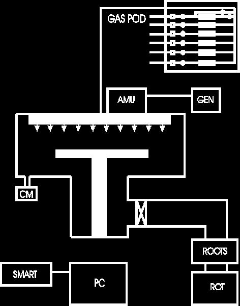
38 PLD system Lasers: Excimer laser. 1 to 100 Hz repetition rates, 15 to 50 ns pulse duration. Optics: UV windows, mirrors, beam splitters. Vacuum chamber, pumps and gauges: High vacuum standard equipments. Gas flow: Oxygen. Target manipulation: Rotation. Substrate holder and heater.
39 Chemical vapor deposition Reactive carrier gases. Transport precursors of desired materials to the substrate surface. Gases react with other gases or decompose to produce stable reaction products and deposit on the substrate. Most versatile deposition techniques. Wide range of chemical reactions, reactants, and applications.
40 Films grown by CVD Single-crystalline thin films. Polycrystalline thin films. Amorphous thin films. Semiconductors (IV, III-V, II-VI), metals, dielectric, superconductors. Microelectronics, optoelectronics, hard and protective coatings.
41 Chemical vapor deposition (CVD) : overview CVD (thermal) APCVD (atmospheric) LPCVD (<10 Pa) VLPCVD (<1.3 Pa) PE CVD (plasma enhanced) Photon-assisted CVD Laser-assisted CVD MOCVD Tensile stress causes concave bending of a thin substrate Deposited film Compressive stress causes convex bending of a thin substate Deposited film
42 Chemical vapor deposition: reaction mechanisms Mass transport of the reactant in the bulk Gas-phase reactions (homogeneous) Mass transport to the surface Adsorption on the surface Surface reactions (heterogeneous) Surface migration Incorporation of film constituents, island formation Desorption of by-products Mass transport of by-produccts in bulk CVD: Diffusive-convective transport of depositing species to a substrate with many intermolecular collisions-driven by a concentration gradient Si SiH4 SiH 4
 Gas Phase")
43 Chemical Vapor Deposition Precursor Reactor Energy Solid Products (thin films and powders) Gas Phase products
44 Precursor Considerations Volatility vapor pressure - simple molecules with high vapor pressure are rare determined by molecular weight and molecularity (degree polymerized) - result of structure and bonding control - temperature, valving Stability, Reactivity, and Safety bond strength, bond dissociation energy - affects process temperature and film composition (purity) thermal stability in storage and delivery into the reactor reactivity of the precursor and byproducts towards other substances (including biological objects like us) Single-Source Precursor providing more than one element into the film simpler delivery system uniform elemental distribution at atomic level possible limited composition range Common Precursors hydrides: MHx - SiH4, GeH4, AlH3(NMe3)2, NH3, PH3... halides: MXy - TiCl4, TaCl5, MoF6, WF6,... metal-organics - metal alkyls: AlMe3, AliBu3, Ti(CH2tBu)4... metal alkoxides: Ti(OiPr)4, [Cu(OtBu)]4... metal dialkylamides: Ti(NMe2)4, Cr(NEt2)4... metal diketonates: Cu(acac)2, Pt(hfac)2... metal carbonyls: Fe(CO)5, Ni(CO)4... others: complexes with alkene, allyl, cyclopentadienyl,... ligands many precursors have mixed ligands
45 Thermally activated CVD Thermal energy (resistance heating, RFheating, infrared radiation). Normal or low pressure. Inorganic materials.
46 Plasma-enhanced CVD Use plasma to ionize and dissociate gases. Enhance growth rate. Lower temperatures. Low pressure. Deposite SiO 2, Si 3 N 4 (temperature<350 o C).


47 PECVD
48 Photo-assisted CVD Use light to enhance the reaction rate. The effect of radiation is either a local heating of the water or a photochemical reaction. Photochemical reaction: Photolytic reaction.

49 Laser Assisted Vapor Deposition He H2 SiH4, SF6, H2
50 Chemical vapor deposition (CVD) : L-CVD The L-CVD method is able to fabricate continuous thin rods and fibres by pulling the substrate away from the stationary laser focus at the linear growth speed of the material while keeping the laser focus on the rod tip, as shown in the Figure. LCVD was first demonstrated for carbon and silicon rods. However, fibers were grown from other substrates including silicon, carbon, boron, oxides, nitrides, carbides, borides, and metals such as aluminium. The L-CVD process can operate at low and high chamber pressures. The growth rate is normally less than 100 µm /s at low chamber pressure (<<1 bar). At high chamber pressure (>1 bar), high growth rate (>1.1 mm/s) has been achieved for small -diameter (< 20 µm) amorphous boron fibers.

51 Laser Assisted Catalytic growth Fig. 2 Schematic of a nanowire growth set up using a combination of laser ablation and vapor-liquid- solid scheme Fig.1 Semiconductor (GaAs) nanowires grown using laser assisted catalytic growth [1ref]. The scale bar corresponds to 50 nm.
52 MOCVD Thermal, glow discharge, ultraviolet radiation. Metalorganic compound (MO) gases or liquids. Epitaxial growth. Semiconductors (III-V, II-VI), high Tc superconductors, dielectric and metal films.

 3 + AsH 3 => 3CH")
53 MOCVD H 2 +AsH 3 RF Coils Gas Exhaust Substrate Mixing Chamber Al(CH 3 ) 3 Ga(CH 3 ) 3 H 2 Ga(CH 3 ) 3 + AsH 3 => 3CH 4 +GaAs
54 Comparison of CVD Thermal CVD: Thermal, inorganic sources. MOCVD: Thermal, organometallic sources. PECVD: Plasma, low temperatures. PACVD: Light, low temperatures, selected area. ALE: Thermal/light, monolayer control.
55 Pressure ranges TACVD: Torr. MOCVD: Torr. PECVD: Torr. PACVD: Torr. ALE: Torr.
56 CVD deposition system Rough vacuum chamber and sensors. Source materials (gas, vapor), gas carriers, gas flow control system. Chemical reaction sources: thermal heating (heaters), plasma generating sources to provide the needed energy for the chemical reactions. Substrates, holders.
57 Growth Mechanism Gas-phase: homogeneous reaction, diffusion of reactants to the substrate surface (mass transport), desorption of reaction by-products from the surface, diffusion of products into the main gas stream. Surface: adsorption of reactants at surface, heterogeneous chemical reactions, surface migration, lattice incorporation.
58 Reduction Many deposition reactions in CVD. Decomposition reaction favoured by the presence of another reactant (usually H 2 ) which helps to remove one or several of the decomposition products. The reversed reaction leads to etching. Reversible reaction. High temperatures.
59 Oxidation The reaction of a vapor-phas substance with oxygen or oxidant (CO 2, N 2 O, NO, O 3 ), resulting in a solid film (oxide). Amorphous dielectric films (SiO 2, Al 2 O 3, TiO 2 ), silicates glasses, oxide semiconductors (ZnO), oxide conductors (SnO 2, In 2 O 3 ), magnetic films (LCMO).
60 Hydrolysis The gaseous compound reacts with externally or in situ formed water vapour leading to the formation of a solid film, usually an oxide. Amorphous and epitaxial films.
61 Nitridation The reaction between a gaseous reactant and ammonia (NH 3 ), nitrogen, hydrazine (N 2 H 4 ) or another nitrogen-containing compound, leading to the formation of a thin nitride film. Silicon nitride (Si 3 N 4 ), oxynitrides (Si x O y N z, Al x O y N z ), semiconducting compound nitrides (BN, AlN, GaN), metallic nitrides (TaN, TiN) and superconducting nitrides (NbN).
62 Chemical Transport The transfer of a relatively non-volatile solid source reacting with a transport agent to form a volatile species.
63 Disproportion The dissociation of a reactant species due to its instability at a lower temperature and the formation of another more stable higher-valence chemical species,yielding at the same time the elemental form of the reactant to be deposited. A typical reaction: GaCl -> (low temp.) Ga + GaCl 3, GaCl<- (high temp.) Ga + GaCl 3.
64 Other reactions in CVD Catalysis: enhanced velocity of a reaction. Synthesis: a solid film results due to the reaction. Photolysis: a reaction due to the absorption of an ultraviolet light. Combined reactions: more than one reactions in a reaction.
65 Atomic Layer Deposition Surface controlled for epitaxial growth of single crystal. Originally designed for compound semiconductors, II-VI, III-V, oxides, nitrides. Epitaxy: Sequential saturated surface reactions to form a monolayer in each sequence. Release or exchange of ligands for saturation in each sequence.
66 ALD Process and Equipments Releases sequential precursor gas pulses to deposit a film one layer at a time. A first precursor gas is introduced into the process chamber and produces a monolayer of gas on the wafer surface. Then a second precursor of gas is introduced into the chamber reacting with the first precursor to produce a monolayer of film on the wafer surface. Two fundamental mechanisms: Chemisorption saturation process Sequential surface chemical reaction process Ref: "Atomic Layer Deposition," Cambridge NanoTech Inc., 24 April 06. <


67 Example: ALD cycle for Al 2 O 3 deposition


68


69


 Ref: \"Atomic")
70 ALD Process and Equipments Releases sequential precursor gas pulses to deposit a film one layer at a time. A first precursor gas is introduced into the process chamber and produces a monolayer of gas on the wafer surface. Then a second precursor of gas is introduced into the chamber reacting with the first precursor to produce a monolayer of film on the wafer surface. Two fundamental mechanisms: Chemisorption saturation process Sequential surface chemical reaction process Example: ALD cycle for Al 2 O 3 deposition (after 3 cycles) Ref: "Atomic Layer Deposition," Cambridge NanoTech Inc., 24 April 06. <

71 Advantages Stoichiometric films with large area uniformity and 3D conformality. Precise thickness control. Low temperature deposition possible. Gentle deposition process for sensitive substrates. Disadvantages Deposition Rate slower than CVD. Number of different material that can be deposited is fair compared to MBE.
72 Plating Deposition of a metal film using chemical reaction. Two types: Electroplating, electroless plating. Electroplating: Electrical contact required, conductive substrates, um thick films. Electroless plating: No electrical contact required, dielectrics and conductors, thin films.
73 Plating Non-vacuum system. Electroplating Electroless Plating Applications Anticorrosion coatings, interconnect metallization formation. Au, Ni coating for wire bonding. Device interconnections.
74 Molecular beam epitaxy Epitaxy: Continuation of crystal structure from the substrate to the film. Single crystalline contaminant-free film. Single atomic layer (monolayer) growth. Small mismatched lattice constant (<1%). Ultrahigh vacuum: <5x10-11 torr. Non-epitaxy films: amorphous or polycrystalline.


75 Molecular Beam Epitaxy
76 MBE deposition system Load lock for substrate loading & unloading. Liquid nitrogen shroud to cool the wall. Substrate heating: clean surface. Film growth: ultrahigh vacuum, shutters to control the flux, in-situ analysis and thickness monitor (RHEED) to control the deposition rate.
77 RHEED Reflection high energy electron diffraction. High energy: > 10 KeV. Small (grazing) angle incidence (<3 ). Low depth penetration: < 100 A. Lateral ordered structure: Surface structure symmetry, lattice constant.

78 RHEED
79 MBE film growth Single crystalline substrate with lattice matching to the film. Heating (500 o C to 550 o C for GaAs, 700 o C to 900 o C for Si) to remove the surface contamination. Layer by layer growth: controlled by high speed shutters and thickness monitor (or RHEED).


80 Quantum Dots Grown Using MBE Electronic Structure of InAs Pyramidal Quantum Dots : AFM Three-dimensional AFM image of CdSe QDs deposited on ZnCdMgSe barriers. The inset shows a histogram of the QD height [ Courtesy: Prof. Tamargo S group- CCNY ].
TMT4320 Nanomaterials November 10 th, Thin films by physical/chemical methods (From chapter 24 and 25)
") 1 TMT4320 Nanomaterials November 10 th, 2015 Thin films by physical/chemical methods (From chapter 24 and 25) 2 Thin films by physical/chemical methods Vapor-phase growth (compared to liquid-phase growth)
1 TMT4320 Nanomaterials November 10 th, 2015 Thin films by physical/chemical methods (From chapter 24 and 25) 2 Thin films by physical/chemical methods Vapor-phase growth (compared to liquid-phase growth)
Physics and Material Science of Semiconductor Nanostructures
 Physics and Material Science of Semiconductor Nanostructures PHYS 570P Prof. Oana Malis Email: omalis@purdue.edu Today Bulk semiconductor growth Single crystal techniques Nanostructure fabrication Epitaxial
Modern Methods in Heterogeneous Catalysis Research: Preparation of Model Systems by Physical Methods
 Modern Methods in Heterogeneous Catalysis Research: Preparation of Model Systems by Physical Methods Methods for catalyst preparation Methods discussed in this lecture Physical vapour deposition - PLD
Physics and Material Science of Semiconductor Nanostructures
 Physics and Material Science of Semiconductor Nanostructures PHYS 570P Prof. Oana Malis Email: omalis@purdue.edu Course website: http://www.physics.purdue.edu/academic_programs/courses/phys570p/ Today
DEPOSITION OF THIN TiO 2 FILMS BY DC MAGNETRON SPUTTERING METHOD
 Chapter 4 DEPOSITION OF THIN TiO 2 FILMS BY DC MAGNETRON SPUTTERING METHOD 4.1 INTRODUCTION Sputter deposition process is another old technique being used in modern semiconductor industries. Sputtering
Introduction to Thin Film Processing
 Introduction to Thin Film Processing Deposition Methods Many diverse techniques available Typically based on three different methods for providing a flux of atomic or molecular material Evaporation Sputtering
Plasma Deposition (Overview) Lecture 1
 Lecture 1") Plasma Deposition (Overview) Lecture 1 Material Processes Plasma Processing Plasma-assisted Deposition Implantation Surface Modification Development of Plasma-based processing Microelectronics needs (fabrication
Plasma Deposition (Overview) Lecture 1 Material Processes Plasma Processing Plasma-assisted Deposition Implantation Surface Modification Development of Plasma-based processing Microelectronics needs (fabrication
CVD: General considerations.
 CVD: General considerations. PVD: Move material from bulk to thin film form. Limited primarily to metals or simple materials. Limited by thermal stability/vapor pressure considerations. Typically requires
Film Deposition Part 1
 1 Film Deposition Part 1 Chapter 11 : Semiconductor Manufacturing Technology by M. Quirk & J. Serda Spring Semester 2013 Saroj Kumar Patra Semidonductor Manufacturing Technology, Norwegian University of
Nanostructure. Materials Growth Characterization Fabrication. More see Waser, chapter 2
 Nanostructure Materials Growth Characterization Fabrication More see Waser, chapter 2 Materials growth - deposition deposition gas solid Physical Vapor Deposition Chemical Vapor Deposition Physical Vapor
EE143 Fall 2016 Microfabrication Technologies. Lecture 6: Thin Film Deposition Reading: Jaeger Chapter 6
 EE143 Fall 2016 Microfabrication Technologies Lecture 6: Thin Film Deposition Reading: Jaeger Chapter 6 Prof. Ming C. Wu wu@eecs.berkeley.edu 511 Sutardja Dai Hall (SDH) 1 Vacuum Basics Units 1 atmosphere
EE C245 ME C218 Introduction to MEMS Design Fall 2007
 EE C245 ME C218 Introduction to MEMS Design Fall 2007 Prof. Clark T.-C. Nguyen Dept. of Electrical Engineering & Computer Sciences University of California at Berkeley Berkeley, CA 94720 Lecture 4: Film
Thin Film Deposition. Reading Assignments: Plummer, Chap 9.1~9.4
 Thin Film Deposition Reading Assignments: Plummer, Chap 9.1~9.4 Thermally grown Deposition Thin Film Formation Thermally grown SiO 2 Deposition SiO 2 Oxygen is from gas phase Silicon from substrate Oxide
Fabrication Technology, Part I
 EEL5225: Principles of MEMS Transducers (Fall 2004) Fabrication Technology, Part I Agenda: Microfabrication Overview Basic semiconductor devices Materials Key processes Oxidation Thin-film Deposition Reading:
Agenda. 1. Atomic Layer Deposition Technology
 Agenda 1. Atomic Layer Deposition Technology 2. What is ALD? Atomic Layer Deposition is invented in 1977 by T. Suntola et al. - New Deposition Method for Electro-Luminescent Display (ZnS:Mn Thin Films)
Wafer holders. Mo- or Ta- made holders Bonding: In (Ga), or In-free (clamped) Quick and easy transfer
, or In-free (clamped) Quick and easy transfer") Wafer holders Mo- or Ta- made holders Bonding: In (Ga), or In-free (clamped) Quick and easy transfer Image: In-free, 3-inch sample holder fitting a quarter of a 2- inch wafer Reflection High Energy Electron
Wafer holders Mo- or Ta- made holders Bonding: In (Ga), or In-free (clamped) Quick and easy transfer Image: In-free, 3-inch sample holder fitting a quarter of a 2- inch wafer Reflection High Energy Electron
Technology for Micro- and Nanostructures Micro- and Nanotechnology
 Lecture 10: Deposition Technology for Micro- and Nanostructures Micro- and Nanotechnology Peter Unger mailto: peter.unger @ uni-ulm.de Institute of Optoelectronics University of Ulm http://www.uni-ulm.de/opto
Repetition: Practical Aspects
 Repetition: Practical Aspects Reduction of the Cathode Dark Space! E x 0 Geometric limit of the extension of a sputter plant. Lowest distance between target and substrate V Cathode (Target/Source) - +
Chemical Vapor Deposition *
 OpenStax-CNX module: m25495 1 Chemical Vapor Deposition * Andrew R. Barron This work is produced by OpenStax-CNX and licensed under the Creative Commons Attribution License 3.0 note: This module was developed
CHAPTER 6: Etching. Chapter 6 1
 Chapter 6 1 CHAPTER 6: Etching Different etching processes are selected depending upon the particular material to be removed. As shown in Figure 6.1, wet chemical processes result in isotropic etching
MICROCHIP MANUFACTURING by S. Wolf
 by S. Wolf Chapter 15 ALUMINUM THIN-FILMS and SPUTTER-DEPOSITION 2004 by LATTICE PRESS CHAPTER 15 - CONTENTS Aluminum Thin-Films Sputter-Deposition Process Steps Physics of Sputter-Deposition Magnetron-Sputtering
Semiconductor Technology
 Semiconductor Technology from A to Z Deposition www.halbleiter.org Contents Contents List of Figures II 1 Deposition 1 1.1 Plasma, the fourth aggregation state of a material............. 1 1.1.1 Plasma
6.5 Optical-Coating-Deposition Technologies
 92 Chapter 6 6.5 Optical-Coating-Deposition Technologies The coating process takes place in an evaporation chamber with a fully controlled system for the specified requirements. Typical systems are depicted
Lecture 6 Plasmas. Chapters 10 &16 Wolf and Tauber. ECE611 / CHE611 Electronic Materials Processing Fall John Labram 1/68
 Lecture 6 Plasmas Chapters 10 &16 Wolf and Tauber 1/68 Announcements Homework: Homework will be returned to you on Thursday (12 th October). Solutions will be also posted online on Thursday (12 th October)
Section 5: Thin Film Deposition part 1 : sputtering and evaporation. Jaeger Chapter 6. EE143 Ali Javey
 Section 5: Thin Film Deposition part 1 : sputtering and evaporation Jaeger Chapter 6 Vacuum Basics 1. Units 1 atmosphere = 760 torr = 1.013x10 5 Pa 1 bar = 10 5 Pa = 750 torr 1 torr = 1 mm Hg 1 mtorr =
Chapter 7 Plasma Basic
 Chapter 7 Plasma Basic Hong Xiao, Ph. D. hxiao89@hotmail.com www2.austin.cc.tx.us/hongxiao/book.htm Hong Xiao, Ph. D. www2.austin.cc.tx.us/hongxiao/book.htm 1 Objectives List at least three IC processes
Metal Deposition. Filament Evaporation E-beam Evaporation Sputter Deposition
 Metal Deposition Filament Evaporation E-beam Evaporation Sputter Deposition 1 Filament evaporation metals are raised to their melting point by resistive heating under vacuum metal pellets are placed on
Etching Issues - Anisotropy. Dry Etching. Dry Etching Overview. Etching Issues - Selectivity
 Etching Issues - Anisotropy Dry Etching Dr. Bruce K. Gale Fundamentals of Micromachining BIOEN 6421 EL EN 5221 and 6221 ME EN 5960 and 6960 Isotropic etchants etch at the same rate in every direction mask
Lecture 1: Vapour Growth Techniques
 PH3EC2 Vapour Growth and Epitaxial Growth Lecturer: Dr. Shinoj V K Lecture 1: Vapour Growth Techniques 1.1 Vapour growth The growth of single crystal materials from the vapour phase. Deposition from the
Chemical Vapor Deposition (CVD)
") Chemical Vapor Deposition (CVD) source chemical reaction film substrate More conformal deposition vs. PVD t Shown here is 100% conformal deposition ( higher temp has higher surface diffusion) t step 1
Chemical Vapor Deposition (CVD) source chemical reaction film substrate More conformal deposition vs. PVD t Shown here is 100% conformal deposition ( higher temp has higher surface diffusion) t step 1
2.1 Template Method Microemulsion Nanostructured Polymer (Copolymer, DNA) Nanostructured Ceramics (AAO, Porous Silica, Zeolite)
 Nanostructured Ceramics (AAO, Porous Silica, Zeolite)") Chapter 1. Characteristics of Nanomaterials Chapter 2. Methodology of Nanomaterials 2.1 Template Method 2.1.1. Microemulsion 2.1.2. Nanostructured Polymer (Copolymer, DNA) 2.1.3. Nanostructured Ceramics
Chapter 1. Characteristics of Nanomaterials Chapter 2. Methodology of Nanomaterials 2.1 Template Method 2.1.1. Microemulsion 2.1.2. Nanostructured Polymer (Copolymer, DNA) 2.1.3. Nanostructured Ceramics
Introduction to Plasma
 What is a plasma? The fourth state of matter A partially ionized gas How is a plasma created? Energy must be added to a gas in the form of: Heat: Temperatures must be in excess of 4000 O C Radiation Electric
Deposition of thin films
 16 th March 2011 The act of applying a thin film to a surface is thin-film deposition - any technique for depositing a thin film of material onto a substrate or onto previously deposited layers. Thin is
Plasma etching. Bibliography
 Plasma etching Bibliography 1. B. Chapman, Glow discharge processes, (Wiley, New York, 1980). - Classical plasma processing of etching and sputtering 2. D. M. Manos and D. L. Flamm, Plasma etching; An
Chapter 7. Plasma Basics
 Chapter 7 Plasma Basics 2006/4/12 1 Objectives List at least three IC processes using plasma Name three important collisions in plasma Describe mean free path Explain how plasma enhance etch and CVD processes
PHYSICAL VAPOR DEPOSITION OF THIN FILMS
 PHYSICAL VAPOR DEPOSITION OF THIN FILMS JOHN E. MAHAN Colorado State University A Wiley-Interscience Publication JOHN WILEY & SONS, INC. New York Chichester Weinheim Brisbane Singapore Toronto CONTENTS
Repetition: Ion Plating
 Repetition: Ion Plating Substrate HV (bis ca. 1kV) Optional ionization system Source Ionized filling gas Source material, ionized or neutral Repetition: Ion Plating Ion Species Separated ion source Ions
Vacuum Pumps. Two general classes exist: Gas transfer physical removal of matter. Mechanical, diffusion, turbomolecular
 Vacuum Technology Vacuum Pumps Two general classes exist: Gas transfer physical removal of matter Mechanical, diffusion, turbomolecular Adsorption entrapment of matter Cryo, sublimation, ion Mechanical
Device Fabrication: Etch
 Device Fabrication: Etch 1 Objectives Upon finishing this course, you should able to: Familiar with etch terminology Compare wet and dry etch processes processing and list the main dry etch etchants Become
ETCHING Chapter 10. Mask. Photoresist
 ETCHING Chapter 10 Mask Light Deposited Substrate Photoresist Etch mask deposition Photoresist application Exposure Development Etching Resist removal Etching of thin films and sometimes the silicon substrate
CHEMICAL VAPOR DEPOSITION (CVD)
") CHEMICAL VAPOR DEPOSITION (CVD) A process of formation of a non-volatile solid film on a substrate from the reaction of vapor phase chemical reactants containing the right proportion of constituents. ELEMETRY
CHEMICAL VAPOR DEPOSITION (CVD) A process of formation of a non-volatile solid film on a substrate from the reaction of vapor phase chemical reactants containing the right proportion of constituents. ELEMETRY
Ionization Techniques Part IV
 Ionization Techniques Part IV CU- Boulder CHEM 5181 Mass Spectrometry & Chromatography Presented by Prof. Jose L. Jimenez High Vacuum MS Interpretation Lectures Sample Inlet Ion Source Mass Analyzer Detector
Combinatorial RF Magnetron Sputtering for Rapid Materials Discovery: Methodology and Applications
 Combinatorial RF Magnetron Sputtering for Rapid Materials Discovery: Methodology and Applications Philip D. Rack,, Jason D. Fowlkes,, and Yuepeng Deng Department of Materials Science and Engineering University
T: +44 (0) W:
 W:") Ultraviolet Deposition of Thin Films and Nanostructures Ian W. Boyd ETC Brunel University Kingston Lane Uxbridge Middx UB8 3PH UK T: +44 (0)1895 267419 W: etcbrunel.co.uk E: ian.boyd@brunel.ac.uk Outline
Ultraviolet Deposition of Thin Films and Nanostructures Ian W. Boyd ETC Brunel University Kingston Lane Uxbridge Middx UB8 3PH UK T: +44 (0)1895 267419 W: etcbrunel.co.uk E: ian.boyd@brunel.ac.uk Outline
LECTURE 5 SUMMARY OF KEY IDEAS
 LECTURE 5 SUMMARY OF KEY IDEAS Etching is a processing step following lithography: it transfers a circuit image from the photoresist to materials form which devices are made or to hard masking or sacrificial
Effect of Spiral Microwave Antenna Configuration on the Production of Nano-crystalline Film by Chemical Sputtering in ECR Plasma
 THE HARRIS SCIENCE REVIEW OF DOSHISHA UNIVERSITY, VOL. 56, No. 1 April 2015 Effect of Spiral Microwave Antenna Configuration on the Production of Nano-crystalline Film by Chemical Sputtering in ECR Plasma
Table of Content. Mechanical Removing Techniques. Ultrasonic Machining (USM) Sputtering and Focused Ion Beam Milling (FIB)
 Sputtering and Focused Ion Beam Milling (FIB)") Table of Content Mechanical Removing Techniques Ultrasonic Machining (USM) Sputtering and Focused Ion Beam Milling (FIB) Ultrasonic Machining In ultrasonic machining (USM), also called ultrasonic grinding,
Table of Content Mechanical Removing Techniques Ultrasonic Machining (USM) Sputtering and Focused Ion Beam Milling (FIB) Ultrasonic Machining In ultrasonic machining (USM), also called ultrasonic grinding,
Solutions for Assignment-6
 Solutions for Assignment-6 Q1. What is the aim of thin film deposition? [1] (a) To maintain surface uniformity (b) To reduce the amount (or mass) of light absorbing materials (c) To decrease the weight
UNIT 3. By: Ajay Kumar Gautam Asst. Prof. Dev Bhoomi Institute of Technology & Engineering, Dehradun
 UNIT 3 By: Ajay Kumar Gautam Asst. Prof. Dev Bhoomi Institute of Technology & Engineering, Dehradun 1 Syllabus Lithography: photolithography and pattern transfer, Optical and non optical lithography, electron,
EE 527 MICROFABRICATION. Lecture 24 Tai-Chang Chen University of Washington
 EE 527 MICROFABRICATION Lecture 24 Tai-Chang Chen University of Washington EDP ETCHING OF SILICON - 1 Ethylene Diamine Pyrocatechol Anisotropy: (100):(111) ~ 35:1 EDP is very corrosive, very carcinogenic,
k T m 8 B P m k T M T
 I. INTRODUCTION AND OBJECTIVE OF THE EXPERIENT The techniques for evaporation of chemicals in a vacuum are widely used for thin film deposition on rigid substrates, leading to multiple applications: production
Chapter 3 Engineering Science for Microsystems Design and Fabrication
 Lectures on MEMS and MICROSYSTEMS DESIGN and MANUFACTURE Chapter 3 Engineering Science for Microsystems Design and Fabrication In this Chapter, we will present overviews of the principles of physical and
Excimer Lasers Currently best UV laser sources Consist two atom types which repel each other eg nobel gas and halide or oxide which normally do not
 Excimer Lasers Currently best UV laser sources Consist two atom types which repel each other eg nobel gas and halide or oxide which normally do not bond But when excited/ionized these atoms attract Bound
Atomic layer deposition of titanium nitride
 Atomic layer deposition of titanium nitride Jue Yue,version4, 04/26/2015 Introduction Titanium nitride is a hard and metallic material which has found many applications, e.g.as a wear resistant coating[1],
Chemistry Instrumental Analysis Lecture 34. Chem 4631
 Chemistry 4631 Instrumental Analysis Lecture 34 From molecular to elemental analysis there are three major techniques used for elemental analysis: Optical spectrometry Mass spectrometry X-ray spectrometry
Section 3: Etching. Jaeger Chapter 2 Reader
 Section 3: Etching Jaeger Chapter 2 Reader Etch rate Etch Process - Figures of Merit Etch rate uniformity Selectivity Anisotropy d m Bias and anisotropy etching mask h f substrate d f d m substrate d f
Thin Film Bi-based Perovskites for High Energy Density Capacitor Applications
 ..SKELETON.. Thin Film Bi-based Perovskites for High Energy Density Capacitor Applications Colin Shear Advisor: Dr. Brady Gibbons 2010 Table of Contents Chapter 1 Introduction... 1 1.1 Motivation and Objective...
Stepwise Solution Important Instructions to examiners:
 (ISO/IEC - 700-005 Certified) SUMMER 05 EXAMINATION Subject Code: 70 Model Answer (Applied Science- Physics) Page No: 0/6 Que. No. Sub. Que. Important Instructions to examiners: ) The answers should be
Wet and Dry Etching. Theory
 Wet and Dry Etching Theory 1. Introduction Etching techniques are commonly used in the fabrication processes of semiconductor devices to remove selected layers for the purposes of pattern transfer, wafer
Nova 600 NanoLab Dual beam Focused Ion Beam IITKanpur
 Nova 600 NanoLab Dual beam Focused Ion Beam system @ IITKanpur Dual Beam Nova 600 Nano Lab From FEI company (Dual Beam = SEM + FIB) SEM: The Electron Beam for SEM Field Emission Electron Gun Energy : 500
Gaetano L Episcopo. Scanning Electron Microscopy Focus Ion Beam and. Pulsed Plasma Deposition
 Gaetano L Episcopo Scanning Electron Microscopy Focus Ion Beam and Pulsed Plasma Deposition Hystorical background Scientific discoveries 1897: J. Thomson discovers the electron. 1924: L. de Broglie propose
EE C245 ME C218 Introduction to MEMS Design Fall 2007
 EE C245 ME C218 Introduction to MEMS Design Fall 2007 Prof. Clark T.-C. Nguyen Dept. of Electrical Engineering & Computer Sciences University of California at Berkeley Berkeley, CA 94720 Lecture 5: ALD,
Chemistry Instrumental Analysis Lecture 17. Chem 4631
 Chemistry 4631 Instrumental Analysis Lecture 17 Introduction to Optical Atomic Spectrometry From molecular to elemental analysis there are three major techniques used for elemental analysis: Optical spectrometry
SEMICONDUCTOR GROWTH TECHNIQUES. Introduction to growth techniques (bulk, epitaxy) Basic concepts in epitaxy (MBE, MOCVD)
 Basic concepts in epitaxy (MBE, MOCVD)") SEMICONDUCTOR GROWTH TECHNIQUES Introduction to growth techniques (bulk, epitaxy) Basic concepts in epitaxy (MBE, MOCVD) Growth Processes Bulk techniques (massive semiconductors, wafers): Si, compounds
SEMICONDUCTOR GROWTH TECHNIQUES Introduction to growth techniques (bulk, epitaxy) Basic concepts in epitaxy (MBE, MOCVD) Growth Processes Bulk techniques (massive semiconductors, wafers): Si, compounds
Preparation of Nanostructures(Příprava Nanostruktur)
") Preparation of Nanostructures (Příprava Nanostruktur) jaroslav.hamrle@vsb.cz September 23, 2013 Outline 1 Introduction 2 Bulk crystal growth 3 Thin film preparation 4 Lateral structures 5 Surface plasma
Preparation of Nanostructures (Příprava Nanostruktur) jaroslav.hamrle@vsb.cz September 23, 2013 Outline 1 Introduction 2 Bulk crystal growth 3 Thin film preparation 4 Lateral structures 5 Surface plasma
Lecture 1. Introduction to Electronic Materials. Reading: Pierret 1.1, 1.2, 1.4,
 Lecture 1 Introduction to Electronic Materials Reading: Pierret 1.1, 1.2, 1.4, 2.1-2.6 Atoms to Operational Amplifiers The goal of this course is to teach the fundamentals of non-linear circuit elements
20.2 Ion Sources. ions electrospray uses evaporation of a charged liquid stream to transfer high molecular mass compounds into the gas phase as MH n
 20.2 Ion Sources electron ionization produces an M + ion and extensive fragmentation chemical ionization produces an M +, MH +, M +, or M - ion with minimal fragmentation MALDI uses laser ablation to transfer
Atmospheric pressure Plasma Enhanced CVD for large area deposition of TiO 2-x electron transport layers for PV. Heather M. Yates
 Atmospheric pressure Plasma Enhanced CVD for large area deposition of TiO 2-x electron transport layers for PV Heather M. Yates Why the interest? Perovskite solar cells have shown considerable promise
A HYDROGEN SENSITIVE Pd/GaN SCHOTTKY DIODE SENSOR
 Journal of Physical Science, Vol. 17(2), 161 167, 2006 161 A HYDROGEN SENSITIVE Pd/GaN SCHOTTKY DIODE SENSOR A.Y. Hudeish 1,2* and A. Abdul Aziz 1 1 School of Physics, Universiti Sains Malaysia, 11800
Clean-Room microfabrication techniques. Francesco Rizzi Italian Institute of Technology
 Clean-Room microfabrication techniques Francesco Rizzi Italian Institute of Technology Miniaturization The first transistor Miniaturization The first transistor Miniaturization The first transistor Miniaturization
3.155J/6.152J Microelectronic Processing Technology Fall Term, 2004
 3.155J/6.152J Microelectronic Processing Technology Fall Term, 2004 Bob O'Handley Martin Schmidt Quiz Nov. 17, 2004 Ion implantation, diffusion [15] 1. a) Two identical p-type Si wafers (N a = 10 17 cm
Ion Implant Part 1. Saroj Kumar Patra, TFE4180 Semiconductor Manufacturing Technology. Norwegian University of Science and Technology ( NTNU )
") 1 Ion Implant Part 1 Chapter 17: Semiconductor Manufacturing Technology by M. Quirk & J. Serda Spring Semester 2014 Saroj Kumar Patra,, Norwegian University of Science and Technology ( NTNU ) 2 Objectives
1 Ion Implant Part 1 Chapter 17: Semiconductor Manufacturing Technology by M. Quirk & J. Serda Spring Semester 2014 Saroj Kumar Patra,, Norwegian University of Science and Technology ( NTNU ) 2 Objectives
Halbleiter. Prof. Yong Lei. Prof. Thomas Hannappel.
 Halbleiter Prof. Yong Lei Prof. Thomas Hannappel yong.lei@tu-ilemnau.de thomas.hannappel@tu-ilmenau.de Important Events in Semiconductors History 1833 Michael Faraday discovered temperature-dependent conductivity
Energetic particles and their detection in situ (particle detectors) Part II. George Gloeckler
 Part II. George Gloeckler") Energetic particles and their detection in situ (particle detectors) Part II George Gloeckler University of Michigan, Ann Arbor, MI University of Maryland, College Park, MD Simple particle detectors Gas-filled
Energetic particles and their detection in situ (particle detectors) Part II George Gloeckler University of Michigan, Ann Arbor, MI University of Maryland, College Park, MD Simple particle detectors Gas-filled
PRINCIPLES OF PLASMA DISCHARGES AND MATERIALS PROCESSING
 PRINCIPLES OF PLASMA DISCHARGES AND MATERIALS PROCESSING Second Edition MICHAEL A. LIEBERMAN ALLAN J, LICHTENBERG WILEY- INTERSCIENCE A JOHN WILEY & SONS, INC PUBLICATION CONTENTS PREFACE xrrii PREFACE
JARA FIT Ferienprakticum Nanoelektronik Experiment: Resonant tunneling in quantum structures
 JARA FIT Ferienprakticum Nanoelektronik 2013 Experiment: Resonant tunneling in quantum structures Dr. Mihail Ion Lepsa, Peter Grünberg Institut (PGI 9), Forschungszentrum Jülich GmbH 1. Introduction The
Pulsed Laser Deposition; laser ablation. Final apresentation for TPPM Diogo Canavarro, MEFT
 Pulsed Laser Deposition; laser ablation Final apresentation for TPPM Diogo Canavarro, 56112 MEFT Summary What is PLD? What is the purpose of PLD? How PLD works? Experimental Setup Processes in PLD The
Chapter 4 Scintillation Detectors
 Med Phys 4RA3, 4RB3/6R03 Radioisotopes and Radiation Methodology 4-1 4.1. Basic principle of the scintillator Chapter 4 Scintillation Detectors Scintillator Light sensor Ionizing radiation Light (visible,
Semiconductor Physics and Devices
 Syllabus Advanced Nano Materials Semiconductor Physics and Devices Textbook Donald A. Neamen (McGraw-Hill) Semiconductor Physics and Devices Seong Jun Kang Department of Advanced Materials Engineering
Fabrication at the nanoscale for nanophotonics
 Fabrication at the nanoscale for nanophotonics Ilya Sychugov, KTH Materials Physics, Kista silicon nanocrystal by electron beam induced deposition lithography Outline of basic nanofabrication methods Devices
Self-Assembled InAs Quantum Dots
 Self-Assembled InAs Quantum Dots Steve Lyon Department of Electrical Engineering What are semiconductors What are semiconductor quantum dots How do we make (grow) InAs dots What are some of the properties
Electrical Discharges Characterization of Planar Sputtering System
 International Journal of Recent Research and Review, Vol. V, March 213 ISSN 2277 8322 Electrical Discharges Characterization of Planar Sputtering System Bahaa T. Chaid 1, Nathera Abass Ali Al-Tememee 2,
Vacuum Technology and film growth. Diffusion Resistor
 Vacuum Technology and film growth Poly Gate pmos Polycrystaline Silicon Source Gate p-channel Metal-Oxide-Semiconductor (MOSFET) Drain polysilicon n-si ion-implanted Diffusion Resistor Poly Si Resistor
Optical Spectroscopies of Thin Films and Interfaces. Dietrich R. T. Zahn Institut für Physik, Technische Universität Chemnitz, Germany
 Optical Spectroscopies of Thin Films and Interfaces Dietrich R. T. Zahn Institut für Physik, Technische Universität Chemnitz, Germany 1. Introduction 2. Vibrational Spectroscopies (Raman and Infrared)
XPS/UPS and EFM. Brent Gila. XPS/UPS Ryan Davies EFM Andy Gerger
 XPS/UPS and EFM Brent Gila XPS/UPS Ryan Davies EFM Andy Gerger XPS/ESCA X-ray photoelectron spectroscopy (XPS) also called Electron Spectroscopy for Chemical Analysis (ESCA) is a chemical surface analysis
E SC 412 Nanotechnology: Materials, Infrastructure, and Safety Wook Jun Nam
 E SC 412 Nanotechnology: Materials, Infrastructure, and Safety Wook Jun Nam Lecture 10 Outline 1. Wet Etching/Vapor Phase Etching 2. Dry Etching DC/RF Plasma Plasma Reactors Materials/Gases Etching Parameters
Etching: Basic Terminology
 Lecture 7 Etching Etching: Basic Terminology Introduction : Etching of thin films and sometimes the silicon substrate are very common process steps. Usually selectivity, and directionality are the first
Carbon nanotubes synthesis. Ing. Eva Košťáková KNT, FT, TUL
 Carbon nanotubes synthesis Ing. Eva Košťáková KNT, FT, TUL Basic parameters: -Temperature (500, 1000 C ) -Pressure (normal, vacuum ) -Gas (ambient, inert atmosphere nitrogen, argon ) -Time (duration, time
Eximer Lasers UV laser sources Consist two atom types which repel each other eg nobel gas and halide or oxide When excited/ionized atoms attract
 Eximer Lasers UV laser sources Consist two atom types which repel each other eg nobel gas and halide or oxide When excited/ionized atoms attract Bound together separated by short distance Call this Excited
Self-study problems and questions Processing and Device Technology, FFF110/FYSD13
 Self-study problems and questions Processing and Device Technology, FFF110/FYSD13 Version 2016_01 In addition to the problems discussed at the seminars and at the lectures, you can use this set of problems
TiO2/sapphire Beam Splitter for High-order Harmonics
 Technical Communication TiO2/sapphire Beam Splitter for High-order Harmonics Y. Sanjo*1, M. Murata*1, Y. Tanaka*1, H. Kumagai*1, and M. Chigane*2 *1 Graduate School of Engineering,Osaka City University,
Ajay Kumar Gautam Asst. Prof. Electronics & Communication Engineering Dev Bhoomi Institute of Technology & Engineering Dehradun UNIT II
 Ajay Kumar Gautam Asst. Prof. Electronics & Communication Engineering Dev Bhoomi Institute of Technology & Engineering Dehradun UNIT II Syllabus EPITAXIAL PROCESS: Epitaxy and its concept, Growth kinetics
X-Ray Photoelectron Spectroscopy (XPS) Prof. Paul K. Chu
 Prof. Paul K. Chu") X-Ray Photoelectron Spectroscopy (XPS) Prof. Paul K. Chu X-ray Photoelectron Spectroscopy Introduction Qualitative analysis Quantitative analysis Charging compensation Small area analysis and XPS imaging
X-Ray Photoelectron Spectroscopy (XPS) Prof. Paul K. Chu X-ray Photoelectron Spectroscopy Introduction Qualitative analysis Quantitative analysis Charging compensation Small area analysis and XPS imaging
Laser matter interaction
 Laser matter interaction PH413 Lasers & Photonics Lecture 26 Why study laser matter interaction? Fundamental physics Chemical analysis Material processing Biomedical applications Deposition of novel structures
Lecture 10 Thin Film Growth
 Lecture 10 Thin Film Growth 1/76 Announcements Homework: Homework Number 2 is returned today, please pick it up from me at the end of the class. Solutions are online. Homework 3 will be set Thursday (2
Sputter Ion Pump (Ion Pump) By Biswajit
 By Biswajit") Sputter Ion Pump (Ion Pump) By Biswajit 08-07-17 Sputter Ion Pump (Ion Pump) An ion pump is a type of vacuum pump capable of reaching pressures as low as 10 11 mbar under ideal conditions. An ion pump
Sputter Ion Pump (Ion Pump) By Biswajit 08-07-17 Sputter Ion Pump (Ion Pump) An ion pump is a type of vacuum pump capable of reaching pressures as low as 10 11 mbar under ideal conditions. An ion pump
Reactive Ion Etching (RIE)
") Reactive Ion Etching (RIE) RF 13.56 ~ MHz plasma Parallel-Plate Reactor wafers Sputtering Plasma generates (1) Ions (2) Activated neutrals Enhance chemical reaction 1 2 Remote Plasma Reactors Plasma Sources
Reactive Ion Etching (RIE) RF 13.56 ~ MHz plasma Parallel-Plate Reactor wafers Sputtering Plasma generates (1) Ions (2) Activated neutrals Enhance chemical reaction 1 2 Remote Plasma Reactors Plasma Sources
EE 5344 Introduction to MEMS CHAPTER 5 Radiation Sensors
 EE 5344 Introduction to MEMS CHAPTER 5 Radiation Sensors 5. Radiation Microsensors Radiation µ-sensors convert incident radiant signals into standard electrical out put signals. Radiant Signals Classification
a. An emission line as close as possible to the analyte resonance line
 Practice Problem Set 5 Atomic Emission Spectroscopy 10-1 What is an internal standard and why is it used? An internal standard is a substance added to samples, blank, and standards. The ratio of the signal
Chapter 3: Thin film deposition and characterization techniques
 Chapter 3: Thin film deposition and characterization techniques 3.1 Introduction: The Material Science and Engineering community s ability to visualize the novel materials with extraordinary combination