DESCRIPTION OF MAIN EQUIPMENT
|
|
|
- Rosalind Taylor
- 6 years ago
- Views:
Transcription

1 The TOKAMAK
2 DESCRIPTION OF MAIN EQUIPMENT ITER is a long pulse Tokamak with elongated plasma and single null poloidal divertor. The nominal inductive operation produces a DT fusion power of 500 MW for a burn length of 400s, with the injection of 50 MW of auxiliary power. The major components of the Tokamak are the superconducting toroidal and poloidal field coils which magnetically confine, shape and control the plasma inside a toroidal vacuum vessel. The magnet system comprises toroidal field (TF) coils, a central solenoid (CS), external poloidal field (PF) coils, and correction coils (CC). The centring force acting on the D-shaped toroidal magnets is reacted by these coils by wedging in the vault formed by their straight sections. The TF coil windings are enclosed in strong cases used also to support the external PF coils. The vacuum vessel is a double-walled structure also supported on the toroidal field coils. The magnet system together with the vacuum vessel and internals are supported by gravity supports, one beneath each TF coil. Inside the vacuum vessel, the internal, replaceable components, including blanket modules, divertor cassettes, and port plugs such as the limiter, heating antennae, test blanket modules, and diagnostics modules, absorb the radiated heat as well as most of the neutrons from the plasma and protect the vessel and magnet coils from excessive nuclear radiation. The shielding blanket design does not preclude its later replacement on the outboard side by a tritium-breeding blanket constrained to the same temperature cooling water as the shielding blanket. The heat deposited in the internal components and in the vessel is rejected to the environment by means of the Tokamak cooling water system (comprising individual heat transfer systems) designed to exclude releases of tritium and activated corrosion products to the environment. Some elements of these heat transfer systems are also employed to bake and consequently clean the plasma-facing surfaces inside the vessel by releasing trapped impurities. The entire Tokamak is enclosed in a cryostat, with thermal shields between the hot components and the cryogenically cooled magnets. The ITER Tokamak Major Ex-Vessel Components PF1 / PF2 Upper CC CS Feeders Cryo Lid Upper Cyl PF3 / PF4 UPSE/UPE/Bellows Side CC EQPE/NBI/Bellows/Ducts CTS DPE/PUMP/Bellows Feeders CTS PF5 / PF6 Lower CC ITER Machine Assembly Assembly Tools Conceptual Design Review Page 16 of 19

3 ITER Tokamak Cross Section

, which are highly energetic outbursts near the plasma edge that, if left uncontrolled, cause the plasma to lose part of")
4 Magnets The 48 elements of the ITER Magnet system will generate a magnetic field some times higher than that of our Earth. The ITER Magnet System comprises 18 superconducting Toroidal Field and 6 Poloidal Field coils, a Central Solenoid, and a set of Correction coils that magnetically confine, shape and control the plasma inside the Vacuum Vessel. Additional coils will be implemented to mitigate Edge Localized Modes (ELMs), which are highly energetic outbursts near the plasma edge that, if left uncontrolled, cause the plasma to lose part of its energy. The power of the magnetic fields required to confine the plasma in the ITER Vacuum Vessel is extreme. For maximum efficiency and to limit energy consumption, ITER uses superconducting magnets that loose their resistance when cooled down to very low temperatures. The Toroidal and Poloidal Field coils lie between the Vacuum Vessel and the Cryostat, where they are cooled and shielded from the heat generating neutrons of the fusion reaction. The superconducting material for both the Central Solenoid and the Toroidal Field coils is an alloy made of Niobium and Tin (Nb3Sn). The Poloidal Field coils and the Correction coils use a different, Niobium-Titanium (NbTi) alloy. In order to achieve superconductivity, all coils are cooled with supercritical Helium in the range of 4 Kelvin (-269 C). One of the 18 Toroidal Field coils.

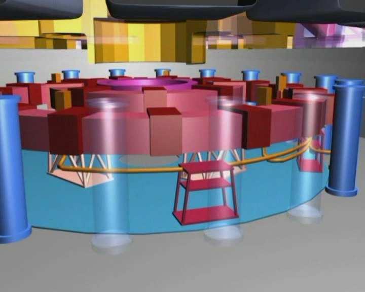
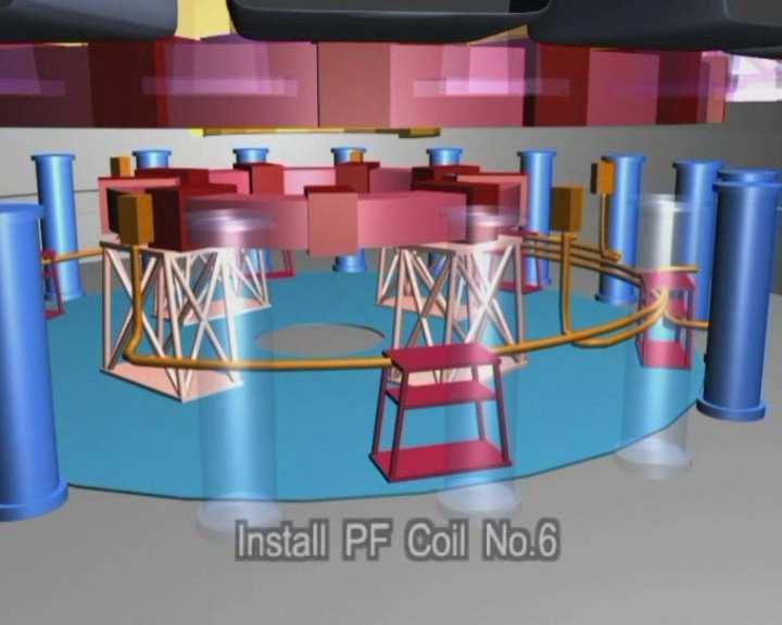
5 Toroidal Field System The 18 Toroidal Field (TF) magnets produce a magnetic field around the torus, whose primary function is to confine the plasma particles. The ITER TF coils are designed to have a total magnetic energy of 41 gigajoules and a maximum magnetic field of 11.8 tesla. The coils will weigh 6540 tons total; besides the Vacuum Vessel, they are the biggest components of the ITER machine. The coils will be made of Cable-In-Conduit superconductors, in which a bundle of superconducting strands is cabled together and cooled by flowing Helium, and contained in a structural jacket. The strands necessary for the ITER TF coils have a total length of kilometres and would span the earth more than three times. Poloidal Field System The Poloidal Field coil system consists of six independent coils placed outside the Toroidal Magnet structure. The Poloidal Field (PF) magnets pinch the plasma away from the walls and contribute in this way to maintaining the plasma's shape and stability. The PF field is induced both by the Magnets and by the current drive in the plasma itself. The Poloidal Field coil system consists of six horizontal coils placed outside the Toroidal Magnet structure. Due to their size, the actual winding of five of the six PF coils will take place in a dedicated, 250-metre long coil winding building on the ITER site in Cadarache. The smallest of the PF coils will be manufactured offsite and delivered finished. The ITER PF coils are also made of Cable-in-Conduit conductors. Two different types of strands are used according to operating requirements, each displaying differences in highcurrent and high-temperature behaviour.

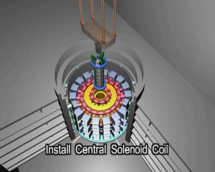
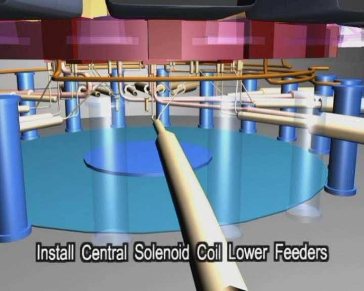
6 The Central Solenoid - the backbone of the Magnet system - is essentially a large transformer Central Solenoid The main plasma current is induced by the changing current in the Central Solenoid which is essentially a large transformer, and the 'backbone' of the Magnet System. It contributes to the inductive flux that drives the plasma, to the shaping of the field lines in the Divertor region, and to vertical stability control. The Central Solenoid is made of six independent coil packs that use a Niobium-Tin (Nb3Sn) Cable-in-Conduit superconducting conductor, held together by a vertical precompression structure. This design enables ITER to access a wide operating window of plasma parameters, enabling the testing of different operating scenarios up to 17 MA and covering inductive and non-inductive operation. Each coil is based on a stack of multiple pancake winding units that minimizes joints. A glass-polyimide electrical insulation, impregnated with epoxy resin, gives a high voltage operating capability, tested up to 29 kv. The conductor jacket material has to resist the large electromagnetic forces arising during operation and be able to demonstrate good fatigue behaviour. The conductor will be produced in unit lengths up to 910 metres. Magnet System Central Solenoid Toroidal Field Coils (18) Poloidal Field Coils (1 6) Correction Coils: 6 Upper 6 side 6 lower 43 superconducting coils - 18 TF coils (16.6 x 9.0 x 2.7, 325 t) - 6 PF coils (to Dia x 1.3, 627 t) - central solenoid (Dia. 4.4 x 17.8, ~1000 t) - 18 correction coils (to 7.9 x 7.2 x 0.8, 27 t) - mechanical attachment, shimmed, keyed, bolted - assembly tolerance low to sub- mm Machine Gravity Supports (18) ITER Machine Assembly Assembly Tools Conceptual Design Review Page 3 of 19


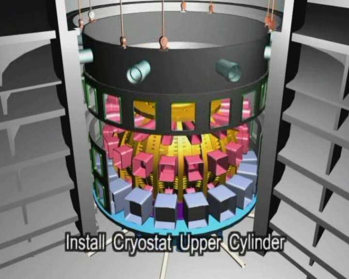
7 Cryostat The entire Vacuum Vessel is enclosed within a Cryostat, or cold box, which provides insulation for the superconducting Magnet system and other components. The ITER Cryostat will be 31 metres tall and nearly 37 metres wide. The Cryostat is a large, stainless steel structure surrounding the Vacuum Vessel and superconducting Magnets, providing a super-cool, vacuum environment. It is made up of two concentric walls connected by horizontal and vertical ribs. The space between the walls is filled with Helium gas at slightly above one atmosphere that acts as thermal barrier. The Cryostat is 31 metres tall and 36.5 metres wide. The Cryostat has many openings, some as large as four metres in diametre, which provide access to the Vacuum Vessel for Cooling systems, Magnet feeders, auxiliary Heating, Diagnostics, and the removal of Blanket and Divertor parts. Large bellows are used between the Cryostat and the Vacuum Vessel to allow for thermal contraction and expansion in the structures. The Cryostat is completely surrounded by a concrete layer known as the bioshield. Above the Cryostat, the bioshield is two metres thick.
8 Cryogenic Pumps Well recessed and shielded from neutrons but inside the divertor port are the torus cryogenic pumps operating at 4.5 K. These have the capacity to pump hydrogenic atoms as well as helium by adsorption and condensation. The pumping performance can be varied and the condensed gases can be removed by heating the pumping panels to 80 K and pumping away the gas released using a roughing pump after a shutter towards the vacuum chamber has been closed. For long plasma pulses, this procedure may be carried out on-line sequentially through all the installed cryogenic pumps in order to limit the amount of hydrogen in each pump below its deflagration level in case of an accidental ingress of oxygen. This limiting amount of hydrogen corresponds to pumping 200 Pam3s-1 of DT for 450 s, with six pumps. Cryostat - Single walled, all-welded structure - SS 304 L - ASME VIII, Div 2 - site fabricated from 40 or 60 sectors - in-situ assembly from 6 sections - assembly tolerance high mm central lid, Dia 10.7 x 3.7 (110 t) main lid, Dia 29.0 x 4.1, 558 t (6 or 9 sectors for transport) upper cyl, Dia 28.6 x 9.1, 583 t (6 or 9 sectors for transport) lower cyl, Dia 28.6 x 9.9, 523 t (6 or 9 sectors for transport) base, Dia 29.0 x 6.0, 1105 t base plug, Dia 4.3 x.06 (6.8 t) ITER Machine Assembly Assembly Tools Conceptual Design Review Page 6 of 19
9 Vacuum Vessel The large stainless steel Vacuum Vessel provides an enclosed, vacuum environment for the fusion reaction. A cut-away of the ITER Vacuum Vessel showing the Blanket modules attached to its inner wall and the Divertor at the bottom. The Vacuum Vessel is a hermetically-sealed steel container inside the Cryostat that houses the fusion reaction and acts as a first safety containment barrier. In its doughnut-shaped chamber, or torus, the plasma particles spiral around continuously without touching the walls. The size of the Vacuum Vessel dictates the volume of the fusion plasma; the larger the vessel, the greater the amount of power that can be produced. The ITER Vacuum Vessel will be twice as large and sixteen times as heavy as any previous tokamak, with an internal diametre of 6 metres. It will measure a little over 19 metres across by 11 metres high, and weigh in excess of 5000 tons.

10 The Vacuum Vessel will have double steel walls, with passages for Cooling Water to circulate between them. The inner surfaces of the Vessel will be covered with Blanket Modules that will provide shielding from the high-energy neutrons produced by the fusion reactions. Some of the Blanket Modules will also be used at later stages to test materials for Tritium Breeding concepts. Forty-four ports will provide access to the Vacuum Vessel for Remote Handling operations, Diagnostic systems, Heating, and Vacuum systems: 18 upper ports, 17 equatorial ports, and 9 lower ports. The ITER Vacuum Vessel with its 44 ports. At 8000 tons, the stainless steel vacuum vessel weighs slightly more than the Eiffel Tower. Vacuum Vessel The vacuum vessel is a component with multiple functions, namely it: provides a boundary consistent with the generation and maintenance of a high quality vacuum, necessary for limiting impurity influx into the plasma; supports the in-vessel components and their resultant mechanical loads; participates in shielding against neutrons, and in removing the corresponding power during a pulse, and moreover in removing the decay heat of all in-vessel components in case of there being no other coolant available; provides a continuous conductive shell for plasma MHD stabilisation with a toroidal one turn resistance of ~8mW; provides all access to the plasma through ports, for diagnostics, heating systems, pumping, water piping, etc; provides the first confinement barrier for tritium and activated dust with a very high reliability.
11 All these functions are central to the operation of ITER and thus require a very robust mechanical design analysed for stresses in all possible normal and off-normal conditions. The vessel is built with two shells linked by ribs and fitted with nuclear radiation shielding material, and ferromagnetic inserts in the shadow of the TF coils to reduce the TF ripple value. To ensure reliable water cooling, two independent loops are used. These can remove by natural convection the decay heat from all in-vessel components (if they are not cooled directly). The vessel water temperature is maintained at 100 C (at 200 C during baking of the in-vessel components), limiting to ~50 C its difference with the in-vessel component cooling temperature. Vacuum Vessel and Port Structures - Double walled, all-welded structure - SS 316L(N) - IG - 9 x 420 tonne 40 sectors - 18 upper, 17 equatorial, 9 divertor port structures - RCC-MR all welded assembly - assembly tolerance mid mm ITER Machine Assembly Assembly Tools Conceptual Design Review Page 4 of 19 Vacuum Vessel Pressure Suppression System In the case of a water pipe rupture inside the vessel, the subsequent chamber pressure will be limited below 0.2 MPa by the opening of rupture disks and communication with a large container located above the Tokamak vacuum vessel and half-filled with water, in which the steam will be condensed (the vacuum vessel pressure suppression system - VVPSS). Simultaneously, liquid water condensed in of flowing into the vessel will be driven into drain tanks located at the bottom of the Tokamak building.
12 Thermal Shield Thermal Shields Cryostat Thermal Shield - SS 304L (main structure) - sub-divided for pre- and final assembly - silver plated panels - cooling tubes doubled for redundancy - ASME (TBD) - bolted assembly - assembly tolerance high mm Vacuum Vessel Thermal Shield Vacuum Vessel Thermal Shield - SS 304L (main structure) - 9 IB, 18 OB sectors - bolted OR welded assembly (TBD) - assembly tolerance mid mm ITER Machine Assembly Assembly Tools Conceptual Design Review Page 5 of 19


13 External Heating Systems The ITER Tokamak will rely on three sources of external heating to bring the plasma to the temperature necessary for fusion. A Neutral Beam Injector and two types of high-frequency electromagnetic waves will help bring the plasma to temperatures exceeding 150 million C.

14 The temperatures inside the ITER Tokamak must reach 150 million Celsius or ten times the temperature at the core of the Sun in order for the gas in the vacuum chamber to reach the plasma state and for the fusion reaction to occur. The hot plasma must then be sustained at these extreme temperatures in a controlled way in order to extract energy. The ITER Tokamak will rely on three sources of external heating that work in concert to provide the input heating power of 50 MW required to bring the plasma to the temperature necessary for fusion. These are neutral beam injection and two sources of high-frequency electromagnetic waves. Ultimately, researchers hope to achieve a "burning plasma" one in which the energy of the Helium nuclei produced by the fusion reaction is enough to maintain the temperature of the plasma. The external heating can then be strongly reduced or switched off altogether. A burning plasma in which at least 50 percent of the energy needed to drive the fusion reaction is generated internally is an essential step to reaching the goal of fusion power generation. Neutral Beam Injection Using injection to heat the fuel in the ITER Tokamak is very much like using steam in the household cappuccino machine to heat milk. Neutral Beam Injectors are used to shoot uncharged high-energy particles into the plasma where, by way of collision, they transfer their energy to the plasma particles. Before injection, Deuterium atoms must be accelerated outside of the Tokamak to a kinetic energy of 1 Mega electron Volt (MeV). Only atoms with a positive or a negative charge can be accelerated by electric field; for this, electrons must be removed from neutral atoms to create a positively-charged ion. The process must then be reversed before injection into the fusion plasma; otherwise the electrically-charged ion would be deflected by the magnetic field of the plasma cage. In Neutral Beam Injection systems, the ions pass through a cell containing gas where they recover their missing electron and can be injected as fast neutrals into the plasma. It's all about kinetic energy - the Neutral Beam Injector accelerates fast neutralized Deuterium particles into the plasma.

15 The large plasma volume at ITER will impose new requirements on this proven method of injection: the particles will have to move three to four times faster than in previous systems in order to penetrate far enough into the plasma, and at these higher rates the positivelycharged ions become difficult to neutralize. At ITER, for the first time, a negatively-charged ion source has been selected to circumvent this problem. Although the negative ions will be easier to neutralize, they will also be more challenging to create and to handle than positive ions. The additional electron that gives the ion its negative charge is only loosely bound, and consequently readily lost. Two Neutral Beam Injectors are currently foreseen for ITER. A third Neutral Beam will be used for diagnostic purposes. Ion Cyclotron Heating The ITER Ion Cyclotron antennae will look a lot like these being installed at JET in the UK Ion and Electron Cyclotron heating methods use radio waves at different frequencies to bring additional heat to the plasma, much in the same way that a microwave oven transfers heat to food through microwaves. In Ion Cyclotron Resonance Heating (ICRH), energy is transferred to the ions in the plasma by a high-intensity beam of electromagnetic radiation with a frequency of 30 to 50MHz. A generator, transmission lines and an antenna are necessary for Ion Cyclotron heating. A generator produces high-power radio frequency waves that are carried along a transmission line to an antenna located in the vacuum vessel, sending the waves into the plasma. Electron Cyclotron Heating Electron Cyclotron Resonance Heating (ECRH) heats the electrons in the plasma with a high-intensity beam of electromagnetic radiation at a frequency of 100 to 200MHz; the resonant frequency of electrons. The electrons in turn transfer the absorbed energy to the ions by collision. The Electron Cyclotron heating system is also used to deposit heat in very specific places in the plasma, as a mechanism to minimize the build-up of certain instabilities that lead to cooling of the plasma. In comparison to the ICRH system, the ECRH has the advantage that the beam can be transmitted through air which simplifies the design and allows the source to be far from the plasma, simplifying maintenance. Power will be provided by powerful, highfrequency gyrotrons as power sources. The ITER design includes the development of a 1 MW gyrotron operating at 170 GHz with a pulse duration of more than 500 s.


16 Blanket Blanket modules provide shielding from the high thermal loads within the Vacuum Vessel and the high-energy neutrons produced by the fusion reactions. In later experiments some modules may be used to test Tritium Breeding concepts. The Blanket covers the interior surfaces of the Vacuum Vessel, providing shielding to the Vessel and the superconducting Magnets from the heat and neutron fluxes of the fusion reaction. The neutrons are slowed down in the Blanket where their kinetic energy is transformed into heat energy and collected by the coolants. In a fusion power plant, this energy will be used for electrical power production. This massive stainless-steel block outside the ITER Headquarters represents the Blanket Shield Module BM 11 that will be part of the ITER Vacuum Vessel wall. For purposes of maintenance on the interior of the Vacuum Vessel, the Blanket wall is modular. It consists of 440 individual segments, each measuring 1x1.5 metres and weighing up to 4.6 tons. Each segment has a detachable first wall which directly faces the plasma and removes the plasma heat load, and a semi-permanent Blanket shield dedicated to the neutron shielding.

17 The ITER Blanket directly faces the hot plasma. Because of its unique physical properties, Beryllium has been chosen as the element to cover the first wall. The rest of the Blanket shield will be made of high-strength copper and stainless steel. At a later stage of the ITER project, test breeding modules will be used to test materials for Tritium Breeding concepts. A future fusion power plant producing large amounts of power will be required to breed all of its own Tritium. ITER will test this essential concept of Tritium self-sustainment. Blanket maintenance The maintenance and repair of a blanket module is performed by first removing it from the vessel. For this purpose, a vehicle, equipped with an end gripper, is positioned along a toroidal rail deployed along the vessel torus centreline. The end gripper is engineered to cut the connection to the water pipe feeders and to unbolt the module, and to bring it to an equatorial maintenance door. At this location it will be transferred into a cask, and subsequently to the hot cell for repair or replacement. The cask operates by docking and undocking to the ports of the vessel and of the hot cell, avoiding contamination to the environment. Similar casks are used for removal of any equipment installed in any equatorial or upper port of the vessel, i.e. heating launcher, diagnostics, or tritium breeding test blanket. Value of each blanket individual segment The value of each blanket individual segment can be evaluated to 700 k


18 The ITER Divertor The Divertor is one of the key components of the ITER machine. Situated along the bottom of the Vacuum Vessel, its function is to extract heat and Helium ash the products of the fusion reaction and other impurities from the plasma, in effect acting like a giant exhaust pipe. It will comprise two main parts: a supporting structure made primarily from stainless steel and the plasma facing component, weighing about 700 tons. The plasma facing component will be made of Tungsten, a high-refractory material. The three plasma-facing components of the ITER Divertor: the inner and the outer vertical targets, and the dome. Located at the very bottom of the Vacuum Vessel, the ITER Divertor is made up of 54 remotely-removable cassettes, each holding three plasma-facing components, or targets. These are the inner and the outer vertical targets, and the dome. The targets are situated at the intersection of magnetic field lines where the high-energy plasma particles strike the components. Their kinetic energy is transformed into heat; the heat flux received by these components is extremely intense and requires active water cooling. The choice of the surface material for the Divertor is an important one. Only very few materials are able to withstand temperatures of up to 3000 C for the projected 20-year lifetime of the ITER machine; these will be tested in ITER. ITER will begin operations with a Carbon fibre-reinforced Carbon composite (CFC) Divertor target. This material presents the advantage of high thermal conductivity and it enables an easier learning process for the first years of ITER operation. A second Divertor set will be made of Tungsten which has the advantage of a lower rate of erosion and thus a longer lifetime.

19 Diagnostics About 50 individual measurement systems will help to control, evaluate and optimize plasma performance in ITER and to further understanding of plasma physics. A Bolometer Camera developed at JET. An extensive diagnostic system will be installed on the ITER machine to provide the measurements necessary to control, evaluate and optimize plasma performance in ITER and to further the understanding of plasma physics. These include measurements of temperature, density, impurity concentration, and particle and energy confinement times. The system will comprise about 50 individual measuring systems drawn from the full range of modern plasma diagnostic techniques, including lasers, X-rays, neutron cameras, impurity monitors, particle spectrometres, radiation bolometers, pressure and gas analysis, and optical fibres. Because of the harsh environment inside the Vacuum Vessel, these systems will have to cope with a range of phenomena not previously encountered in diagnostic implementation, while all the while performing with great accuracy and precision. The levels of neutral particle flux, neutron flux and fluence will be respectively about 5, 10 and 10,000 times higher than the harshest experienced in today's machines. The pulse length of the fusion reaction - or the amount of time the reaction is sustained - will be about 100 times longer.
20 EXTERNAL SYSTEMS


21 Vacuum System With a volume of 1400 m³ and 8500 m³ respectively, the ITER Vacuum Vessel and Cryostat range amongst the largest Vacuum Systems ever built. Sophisticated techniques will be necessary for the monitoring and maintenance of these systems: once in operation, there will no longer be access to the machine. Vacuum pumping is required prior to starting the fusion reaction to eliminate all sources of organic molecules that would otherwise be broken up in the hot plasma. Vacuum pumping is also required to create low density, about one million times lower than the density of air. Mechanical pumps and powerful cryogenic pumps evacuate the air out of the Vessel and the Cryostat until the pressure inside has dropped to one millionth of normal atmospheric pressure. Considering the volume of ITER this operation will take 24 to 48 hours. The main pumping systems are the eight torus exhaust pumps, the four cryopumps for the Neutral Beam Injection systems used in plasma heating, and the two cryopumps for the ITER Cryostat and the contained superconducting Magnets. They will be cooled with supercritical Helium. The complex pumps have been tailored for the very specific applications and requirements at ITER. Illustration of the torus exhaust pumping system geometry, showing the four pumping ports with two cryopumps each. The ITER model cryopump tested at the TIMO test facility in Karlsruhe, Germany.

22 Remote Handling Remote handling will have an important role to play in the ITER Tokamak. When operation begins, it will be impossible to make changes, conduct inspections, or repair any of the Tokamak components in the activated areas other than by remote handling. Very reliable and robust remote handling techniques will be necessary to manipulate and exchange components weighing up to 50 tons. The reliability of these techniques will also impact the length of the machine's shut-down phases. All remote handling techniques developed for ITER operate on the same principle. A remote manipulator is used to detach the component; the component is removed through a port and placed into the docked transport cask; a temporary door is placed over the Vacuum Vessel access port; and the cask is closed to prevent contamination. The cask is moved on air bearings along to the Hot Cell. A similar docking occurs at the Hot Cell and the component is removed to be repaired or replaced. The process is then reversed to bring that component back to the Vacuum Vessel. The smooth operation of the ITER machine relies very much on the Remote Handling System. Here, one of the 440 Blanket Modules is being exchanged.

23 Power Supply Electricity requirements for the ITER plant and facilities will range from 110 MW to up to 620 MW for peak periods of 30 seconds during plasma operation. Power will be provided through the 400 kv circuit that already supplies the nearby CEA Cadarache site - a one-kilometre extension will be enough to link the ITER plant into the network. ITER will have a steady state distribution system to supply the electricity needed to operate the entire plant, including offices and the operational facilities. The Cooling Water and Cryogenic systems will together absorb about 80% of this supply. A second pulsed power system will be used during plasma operation to provide the superconducting Magnet coils and the Heating and current drive systems with the large amount of power that they need. Electricity from the 400 kv circuit will be transformed to an intermediate level (69 kv) via 3 step-down transformers. Emergency backup power for the ITER plant and facilities will be covered by two diesel generators. The ITER Power Converter Prototype tested in 1998

24 Fuel Cycle The fuels used in ITER will be processed in a closed cycle. The fusion reaction in the ITER Tokamak will be powered with Deuterium and Tritium, two isotopes of Hydrogen. ITER will be the first fusion machine fully designed for Deuterium- Tritium operation. Commissioning will happen in three phases: Hydrogen operation, followed by Deuterium operation, and finally full Deuterium-Tritium operation. As a first step to starting the fusion reaction, all air and any impurities must be evacuated from the Vacuum Vessel. The powerful Magnets that will help to confine and control the plasma are then turned on and the low-density gaseous fuel is introduced into the Vacuum Vessel by a gas injection system. Once the fuel has been introduced into the vacuum chamber, an electrical current is applied to the system which causes the gas to break down electrically, become ionized, and form a plasma. The "closed DT loop" fuelling cycle of ITER. Stored Deuterium and Tritium are introduced into the vacuum chamber where only a small percentage of the fuel is consumed. The plasma exhaust is removed and processed through an isotope separation system that extracts out the fusion fuels for reinjection into the fuelling cycle.
25 Segregation of tritium-containing equipment in separated structures, with limitation of the local inventory and robust confinement barriers, is appropriate for safety reasons. The storage of D2, DT and T2 is achieved in many parallel canisters, and adsorbed on ZrCo beds, which can deliver rapidly the required flow for plasma fuelling. Their tritium content is measured by calorimetry with around 1% accuracy

26 Hot Cell Facility The Hot Cell facility will be necessary at ITER to provide a secure environment for the processing, repair or refurbishment, testing, and disposal of components that have become activated by neutron exposure. Although no radioactive products are produced by the fusion reaction itself, energetic neutrons interacting with the walls of the Vacuum Vessel will 'activate' these materials over time. Also, materials can become contaminated by Beryllium and Tungsten dust, and Tritium. Heavy refurbishment operations within the Hot Cell facility will be performed by Remote Handling systems capable of handling components up to the size of a school bus. The Hot Cell facility will also house the remote handling equipment for simulation and rehearsal of operations. The Hot Cell facility will also perform the removal of Tritium from tritiated components and materials. This operation will be housed in a safe, confined, and shielded area containing analytical systems for Tritium measurement, and a detritiation system for gaseous streams in order to minimize releases and waste. All waste materials will be treated, packaged, and temporarily stored in the Hot Cell facility before being handed over to the French authorities. The current design of the Hot Cell facility. The cubic metre building is a substantial, stand-alone structure comprises four floors above ground and one full basement.


27 Cooling Water ITER will be equipped with a Cooling Water System to manage the heat generated during operation of the Tokamak. Water from the nearby Canal de Provence will be used to remove heat from the Vacuum Vessel and its components, and to cool the Diagnostics, Heating, Power, and Cryogenic systems. The Cooling Water System is separated into two closed heat transfer circuits plus a Cooling Tower open circuit. A diagram of the ITER Cooling Water System. The water flows from the ITER plant to primary and secondary heat exchangers that reduce the water temperature from its maximum value to 50 C. The heat is released to the environment through the Cooling Tower at an average thermal power of 450 MW during plasma operation. As ITER is a research facility and not a power plant, most of the cooling water will simply evaporate in the Cooling Towers. The remaining water passes through a series of cooling basins. A first basin collects the outlet from the plant. The water is then tested for various parameters such as temperature (maximum 30 C), ph, hydrocarbons, chlorides, sulpha tes and Tritium. These results are submitted to the local authorities. Only clean water is released into the Durance River

28 Tritium Breeding Tritium and Deuterium are two isotopes of Hydrogen that will be used to fuel the fusion reaction in ITER. While Deuterium can be extracted from seawater in virtually boundless quantities, the supply of Tritium in the Earth's crust is limited, estimated currently at twenty kilos. A second source of Tritium fortunately exists: Tritium can be produced within the tokamak when neutrons escaping the plasma interact with a specific element Lithium contained in the Blanket. This concept of 'breeding' Tritium during the fusion reaction is an important one for the future needs of a large-scale fusion power plant. View of a typical TBM test port cell arrangement. ITER will procure the Tritium "fuel" necessary for its expected 20-year lifetime from the global inventory. But for DEMO, the next step on the way to commercial fusion power, about 300g of Tritium will be required per day to produce 800 MW of electrical power. No sufficient external source of Tritium exists for fusion energy development beyond ITER, making the successful development of Tritium Breeding essential for the future of fusion energy. ITER will provide a unique opportunity to test mockups of breeding blankets, called Test Blanket Modules, in a real fusion environment. Within these test blankets, viable techniques for ensuring Tritium breeding self-sufficiency will be explored.

29 PROJECT COSTS WBS Package Sub package 15% increase 1.1 Magnet systems 1383, Vacuum Vessel 414, Blanket System 294, Divertor 143, Machine Assembly 159, Cryostat 132, Thermal shields 49, Vacuum pump & fuelling 70,55 Machine Core Totals 2648, RH Equipment 195, Cooling water 255, Tritium plant 141, Cryoplant etc 166, Power supplies 376, Buildings etc 699,66 Auxiliaries totals 1835, IC H&CD 59, EC H&CD 138, NB H&CD 204,93 H and CD totals 402,79 5,5 Diagnostics 237, CODAC 86,25 Diagnostics & CODAC total 323,44 Totals Machine Core Totals 2648,75 Auxiliaries totals 1835,75 H and CD totals 402,79 Diag & CODAC total 323,44 Total 5210,73
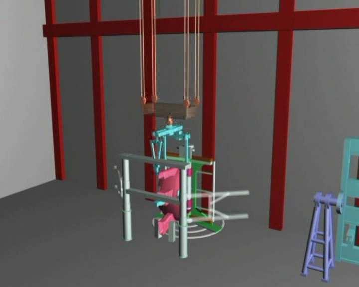
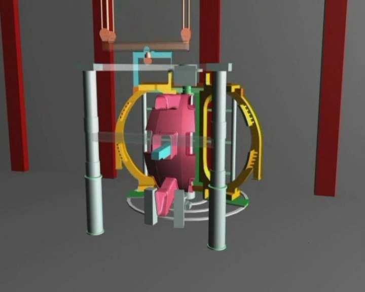
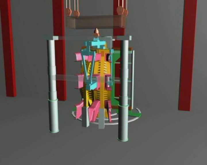
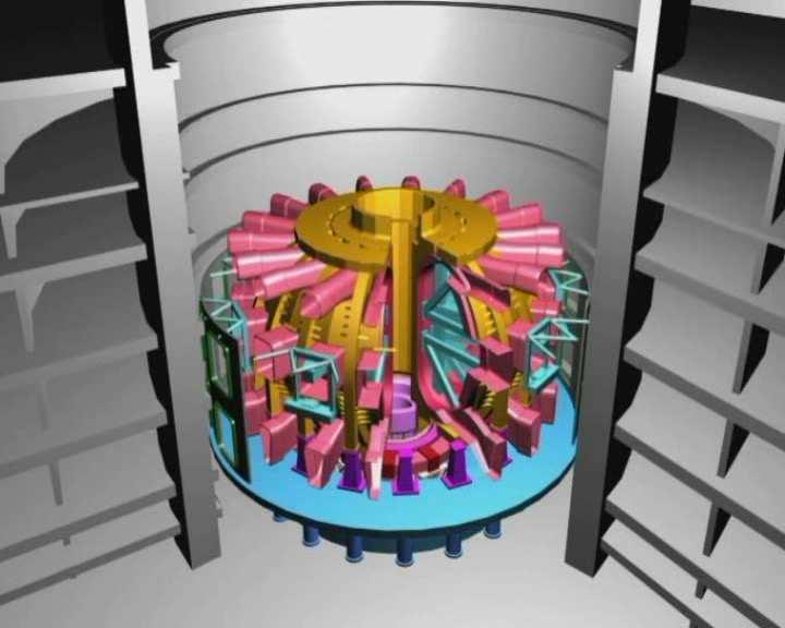
30 ASSEMBLY

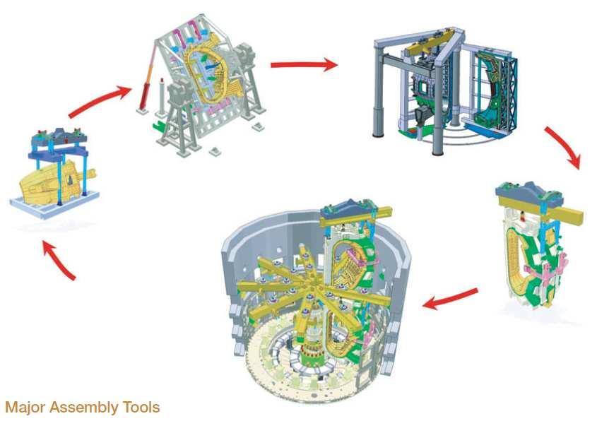
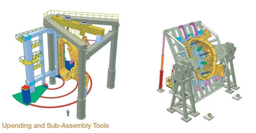
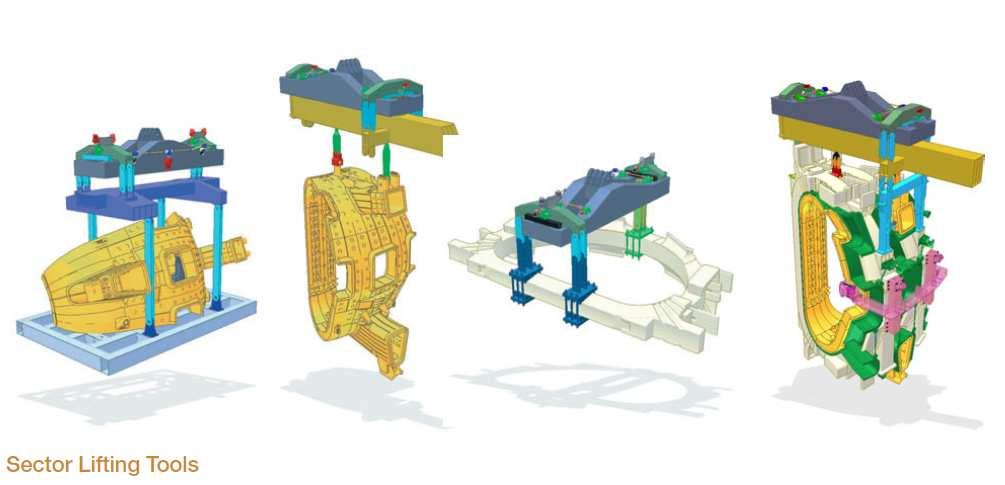
31 Assembly Major tools
32

33 Assembly Hall Layout Major Tools ITER Machine Assembly Assembly Tools Conceptual Design Review Page 9 of 19

34 Assembly Schedule


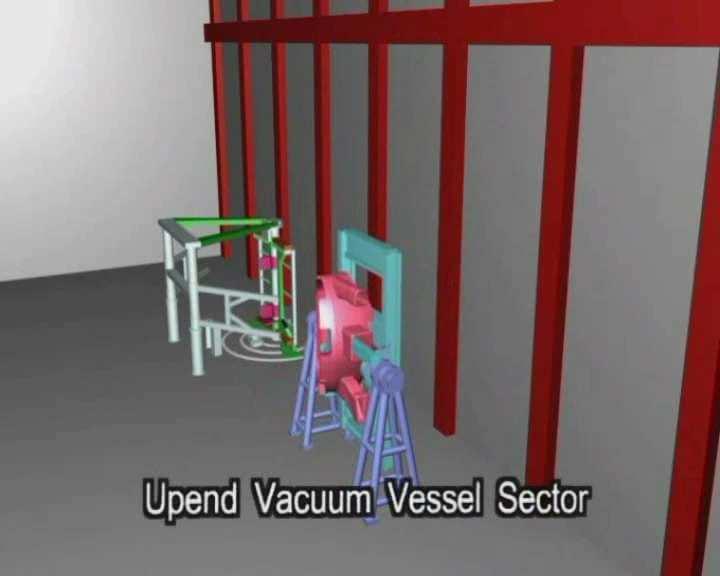
35 Assembly Procedure A film shows the phases of the assembly process from assembly hall to tokamak hall and inside the tokamak hall : Video+2+-+Assembly+Video.avi The main phases are summarized hereafter

36
37
Physics of fusion power. Lecture 14: Anomalous transport / ITER
 Physics of fusion power Lecture 14: Anomalous transport / ITER Thursday.. Guest lecturer and international celebrity Dr. D. Gericke will give an overview of inertial confinement fusion.. Instabilities
Nuclear Energy in the Future. The ITER Project. Brad Nelson. Chief Engineer, US ITER. Presentation for NE-50 Symposium on the Future of Nuclear Energy
 Nuclear Energy in the Future The ITER Project Brad Nelson Chief Engineer, US ITER Presentation for NE-50 Symposium on the Future of Nuclear Energy November 1, 2012 Fusion research is ready for the next
Nuclear Fusion and ITER
 Nuclear Fusion and ITER C. Alejaldre ITER Deputy Director-General Cursos de Verano UPM Julio 2, 2007 1 ITER the way to fusion power ITER ( the way in Latin) is the essential next step in the development
Toward the Realization of Fusion Energy
 Toward the Realization of Fusion Energy Nuclear fusion is the energy source of the sun and stars, in which light atomic nuclei fuse together, releasing a large amount of energy. Fusion power can be generated
Jacob s Ladder Controlling Lightning
 Host: Fusion specialist: Jacob s Ladder Controlling Lightning PART 1 Jacob s ladder demonstration Video Teacher resources Phil Dooley European Fusion Development Agreement Peter de Vries European Fusion
Role and Challenges of Fusion Nuclear Science and Technology (FNST) toward DEMO
 toward DEMO") Role and Challenges of Fusion Nuclear Science and Technology (FNST) toward DEMO Mohamed Abdou Distinguished Professor of Engineering and Applied Science (UCLA) Director, Center for Energy Science & Technology
Role and Challenges of Fusion Nuclear Science and Technology (FNST) toward DEMO Mohamed Abdou Distinguished Professor of Engineering and Applied Science (UCLA) Director, Center for Energy Science & Technology
HT-7U* Superconducting Tokamak: Physics design, engineering progress and. schedule
 1 FT/P2-03 HT-7U* Superconducting Tokamak: Physics design, engineering progress and schedule Y.X. Wan 1), P.D. Weng 1), J.G. Li 1), Q.Q. Yu 1), D.M. Gao 1), HT-7U Team 1) Institute of Plasma Physics, Chinese
Conceptual Design of CFETR Tokamak Machine
 Japan-US Workshop on Fusion Power Plants and Related Advanced Technologies February 26-28, 2013 at Kyoto University in Uji, JAPAN Conceptual Design of CFETR Tokamak Machine Yuntao Song for CFETR Design
ITER DIAGNOSTIC PORT PLUG DESIGN. N H Balshaw, Y Krivchenkov, G Phillips, S Davis, R Pampin-Garcia
 N H Balshaw, Y Krivchenkov, G Phillips, S Davis, R Pampin-Garcia UKAEA, Culham Science Centre, Abingdon, Oxon,OX14 3DB, UK, nick.balshaw@jet.uk Many of the ITER diagnostic systems will be mounted in the
The Path to Fusion Energy creating a star on earth. S. Prager Princeton Plasma Physics Laboratory
 The Path to Fusion Energy creating a star on earth S. Prager Princeton Plasma Physics Laboratory The need for fusion energy is strong and enduring Carbon production (Gton) And the need is time urgent Goal
EU PPCS Models C & D Conceptual Design
 Institut für Materialforschung III EU PPCS Models C & D Conceptual Design Presented by P. Norajitra, FZK 1 PPCS Design Studies Strategy definition [D. Maisonnier] 2 models with limited extrapolations Model
Mission Elements of the FNSP and FNSF
 Mission Elements of the FNSP and FNSF by R.D. Stambaugh PERSISTENT SURVEILLANCE FOR PIPELINE PROTECTION AND THREAT INTERDICTION Presented at FNST Workshop August 3, 2010 In Addition to What Will Be Learned
Unpressurized steam reactor. Controlled Fission Reactors. The Moderator. Global energy production 2000
 From last time Fission of heavy elements produces energy Only works with 235 U, 239 Pu Fission initiated by neutron absorption. Fission products are two lighter nuclei, plus individual neutrons. These
Studies of Next-Step Spherical Tokamaks Using High-Temperature Superconductors Jonathan Menard (PPPL)
") Studies of Next-Step Spherical Tokamaks Using High-Temperature Superconductors Jonathan Menard (PPPL) 22 nd Topical Meeting on the Technology of Fusion Energy (TOFE) Philadelphia, PA August 22-25, 2016
Studies of Next-Step Spherical Tokamaks Using High-Temperature Superconductors Jonathan Menard (PPPL) 22 nd Topical Meeting on the Technology of Fusion Energy (TOFE) Philadelphia, PA August 22-25, 2016
ITER - the decisive step towards Fusion Energy. DPG - Bonn - March 15 th Guenter Janeschitz
 ITER - the decisive step towards Fusion Energy DPG Bonn March 15 th 2010 Guenter Janeschitz Senior Scientific Advisor for Technical Integration (SSATI) to the PDDG ITER Organization, Route de Vinon, CS
Chapter IX: Nuclear fusion
 Chapter IX: Nuclear fusion 1 Summary 1. General remarks 2. Basic processes 3. Characteristics of fusion 4. Solar fusion 5. Controlled fusion 2 General remarks (1) Maximum of binding energy per nucleon
MELCOR Analysis of Helium/Water/Air Ingress into ITER Cryostat and Vacuum Vessel
 TM-2926-1 MELCOR Analysis of Helium/Water/Air Ingress into ITER Cryostat and Vacuum Vessel C. H. Sheng and L. L. Spontón Studsvik Nuclear AB, SE-611 82 Nyköping, Sweden chunhong.sheng@studsvik.se Abstract
Spherical Torus Fusion Contributions and Game-Changing Issues
 Spherical Torus Fusion Contributions and Game-Changing Issues Spherical Torus (ST) research contributes to advancing fusion, and leverages on several game-changing issues 1) What is ST? 2) How does research
Possibilities for Long Pulse Ignited Tokamak Experiments Using Resistive Magnets
 PFC/JA-91-5 Possibilities for Long Pulse Ignited Tokamak Experiments Using Resistive Magnets E. A. Chaniotakis L. Bromberg D. R. Cohn April 25, 1991 Plasma Fusion Center Massachusetts Institute of Technology
Local organizer. National Centralized Tokamak
 US/Japan Workshop on MHD Stability Control and Related Confinement of Toroidal Plasmas, 6-8 February 2006, JAEA-Naka, Japan with ITPA meeting of MHD Topical Group, 6-9 February Venue and Dates The workshop
DEMO Concept Development and Assessment of Relevant Technologies. Physics and Engineering Studies of the Advanced Divertor for a Fusion Reactor
 FIP/3-4Rb FIP/3-4Ra DEMO Concept Development and Assessment of Relevant Technologies Y. Sakamoto, K. Tobita, Y. Someya, H. Utoh, N. Asakura, K. Hoshino, M. Nakamura, S. Tokunaga and the DEMO Design Team
Innovative fabrication method of superconducting magnets using high T c superconductors with joints
 Innovative fabrication method of superconducting magnets using high T c superconductors with joints (for huge and/or complicated coils) Nagato YANAGI LHD & FFHR Group National Institute for Fusion Science,
1 FT/P5-15. Assessment of the Shielding Efficiency of the HCLL Blanket for a DEMOtype Fusion Reactor
 1 FT/P5-15 Assessment of the Shielding Efficiency of the HCLL Blanket for a DEMOtype Fusion Reactor J. Jordanova 1), U. Fischer 2), P. Pereslavtsev 2), Y. Poitevin 3), J. F. Salavy 4), A. Li Puma 4), N.
12 Moderator And Moderator System
 12 Moderator And Moderator System 12.1 Introduction Nuclear fuel produces heat by fission. In the fission process, fissile atoms split after absorbing slow neutrons. This releases fast neutrons and generates
Plasma & Fusion on Earth: merging age-old natural phenomena into your present and future
 Plasma & Fusion on Earth: merging age-old natural phenomena into your present and future Presented by Rick Lee Chief Operator, DIII-D Operations Manager, Energy/Fusion Outreach Program General Atomics
Atomic physics in fusion development
 Atomic physics in fusion development The next step in fusion development imposes new requirements on atomic physics research by R.K. Janev In establishing the scientific and technological base of fusion
Issues for Neutron Calculations for ITER Fusion Reactor
 Introduction Issues for Neutron Calculations for ITER Fusion Reactor Erik Nonbøl and Bent Lauritzen Risø DTU, National Laboratory for Sustainable Energy Roskilde, Denmark Outline 1. Fusion development
Tokamak Divertor System Concept and the Design for ITER. Chris Stoafer April 14, 2011
 Tokamak Divertor System Concept and the Design for ITER Chris Stoafer April 14, 2011 Presentation Overview Divertor concept and purpose Divertor physics General design considerations Overview of ITER divertor
JET and Fusion Energy for the Next Millennia
 JET and Fusion Energy for the Next Millennia JET Joint Undertaking Abingdon, Oxfordshire OX14 3EA JG99.294/1 Talk Outline What is Nuclear Fusion? How can Fusion help our Energy needs? Progress with Magnetic
INTRODUCTION TO MAGNETIC NUCLEAR FUSION
 INTRODUCTION TO MAGNETIC NUCLEAR FUSION S.E. Sharapov Euratom/CCFE Fusion Association, Culham Science Centre, Abingdon, Oxfordshire OX14 3DB, UK With acknowledgments to B.Alper for use of his transparencies
1 FT/P7-5. Engineering Feature in the Design of JT-60SA
 1 FT/P7-5 Engineering Feature in the Design of JT-60SA M. Matsukawa 1), JA-EU satellite tokamak working group and the JT60-SA design team 1) Japan Atomic Energy Agency, Naka, Ibaraki-ken, 311-0193 Japan
Tritium Safety of Russian Test Blanket Module
 Tritium Safety of Russian Test Blanket Module V.K. Kapyshev, V.G. Kovalenko, Y.S. Strebkov N.A. Dollezhal Research and Development Institute of Power Engineering, PO Box 788, Moscow 101000, Russia Abstract
VACUUM VESSEL LOWER PORT PENETRATIONS & IN VESSEL VIEWING PORT EXTENSION
 VACUUM VESSEL LOWER PORT PENETRATIONS & IN VESSEL VIEWING PORT EXTENSION 1. Purpose Call for Nomination (C4N) Ref. IO/CFT/18/15702/JPK Summary of Technical Specifications The purpose of the contract is
Physics and Engineering Studies of the Advanced Divertor for a Fusion Reactor
 1 FIP/3-4Ra Physics and Engineering Studies of the Advanced Divertor for a Fusion Reactor N. Asakura 1, K. Hoshino 1, H. Utoh 1, K. Shinya 2, K. Shimizu 3, S. Tokunaga 1, Y.Someya 1, K. Tobita 1, N. Ohno
Technological and Engineering Challenges of Fusion
 Technological and Engineering Challenges of Fusion David Maisonnier and Jim Hayward EFDA CSU Garching (david.maisonnier@tech.efda.org) 2nd IAEA TM on First Generation of FPP PPCS-KN1 1 Outline The European
The Design and Fabrication of a 6 Tesla EBIT Solenoid
 LBNL-40462 SCMAG-593 The Design and Fabrication of a 6 Tesla EBIT Solenoid 1. Introduction M. A. Green a, S. M. Dardin a, R. E. Marrs b, E. Magee b, S. K. Mukhergee a a Lawrence Berkeley National Laboratory,
A Faster Way to Fusion
 A Faster Way to Fusion 2017 Tokamak Energy Tokamak Energy Ltd Company Overview April 2018 Our Mission To deliver to mankind a cheap, safe, secure and practically limitless source of clean energy fusion
Experimental Facility to Study MHD effects at Very High Hartmann and Interaction parameters related to Indian Test Blanket Module for ITER
 Experimental Facility to Study MHD effects at Very High Hartmann and Interaction parameters related to Indian Test Blanket Module for ITER P. Satyamurthy Bhabha Atomic Research Centre, India P. Satyamurthy,
ESS TARGET STATION AN OVERVIEW OF THE MONOLITH LAYOUT AND DESIGN
 ESS TARGET STATION AN OVERVIEW OF THE MONOLITH LAYOUT AND DESIGN R. Linander, S. Gallimore, M. Göhran, C. Kharoua, F. Mezei, P. Nilsson, E. Pitcher, F. Plewinski, P. Sabbagh, European Spallation Source
Fusion Development Facility (FDF) Mission and Concept
 Mission and Concept") Fusion Development Facility (FDF) Mission and Concept Presented by R.D. Stambaugh PERSISTENT SURVEILLANCE FOR PIPELINE PROTECTION AND THREAT INTERDICTION University of California Los Angeles FNST Workshop
Fusion Development Facility (FDF) Mission and Concept Presented by R.D. Stambaugh PERSISTENT SURVEILLANCE FOR PIPELINE PROTECTION AND THREAT INTERDICTION University of California Los Angeles FNST Workshop
Material, Design, and Cost Modeling for High Performance Coils. L. Bromberg, P. Titus MIT Plasma Science and Fusion Center ARIES meeting
 Material, Design, and Cost Modeling for High Performance Coils L. Bromberg, P. Titus MIT Plasma Science and Fusion Center ARIES meeting Tokamak Concept Improvement Cost minimization Decrease cost of final
JOINTS FOR SUPERCONDUCTING MAGNETS
 JOINTS FOR SUPERCONDUCTING MAGNETS Patrick DECOOL Association EURATOM-CEA, CEA/DSM/IRFM 0 Large machines for fusion deals with Cable In Conduit Conductors (CICC) ITER Each conductor is composed of 1000
Neutronic Activation Analysis for ITER Fusion Reactor
 Neutronic Activation Analysis for ITER Fusion Reactor Barbara Caiffi 100 Congresso Nazionale SIF 1 Outlook Nuclear Fusion International Thermonuclear Experimental Reactor (ITER) Neutronics Computational
Tritium Inventories and Tritium Safety Design Principles for the Fuel cycle of ITER
 Tritium Inventories and Tritium Safety Design Principles for the Fuel cycle of ITER I. R. Cristescu 1), I. Cristescu 1), L. Doerr 1), M. Glugla 1), D. Murdoch 2), 1) Forschungszentrum Karlsruhe, Tritium
Der Stellarator Ein alternatives Einschlusskonzept für ein Fusionskraftwerk
 Max-Planck-Institut für Plasmaphysik Der Stellarator Ein alternatives Einschlusskonzept für ein Fusionskraftwerk Robert Wolf robert.wolf@ipp.mpg.de www.ipp.mpg.de Contents Magnetic confinement The stellarator
Perspective on Fusion Energy
 Perspective on Fusion Energy Mohamed Abdou Distinguished Professor of Engineering and Applied Science (UCLA) Director, Center for Energy Science & Technology (UCLA) President, Council of Energy Research
Status of the Concept Design of CFETR Tokamak Machine
 Status of the Concept Design of CFETR Tokamak Machine Tokamak Machine Design Team Presented by Songtao WU Slide 1 Outline Guideline of the Tokamak Design Magnet Configuration and Preliminary Analysis VV
for the French fusion programme
 The ITER era : the 10 year roadmap for the French fusion programme E. Tsitrone 1 on behalf of IRFM and Tore Supra team 1 : CEA, IRFM, F-13108 Saint-Paul-lez-Durance, France Association EURATOM-CEA TORE
Nuclear Fusion 1 of 24 Boardworks Ltd 2011
 Nuclear Fusion 1 of 24 Boardworks Ltd 2011 2 of 24 Boardworks Ltd 2011 How do we get energy from atoms? 3 of 24 Boardworks Ltd 2011 Energy is produced from atoms in power stations using the process of
Magnetic Confinement Fusion and Tokamaks Chijin Xiao Department of Physics and Engineering Physics University of Saskatchewan
 The Sun Magnetic Confinement Fusion and Tokamaks Chijin Xiao Department of Physics and Engineering Physics University of Saskatchewan 2017 CNS Conference Niagara Falls, June 4-7, 2017 Tokamak Outline Fusion
Neutral beam plasma heating
 Seminar I b 1 st year, 2 nd cycle program Neutral beam plasma heating Author: Gabrijela Ikovic Advisor: prof.dr. Tomaž Gyergyek Ljubljana, May 2014 Abstract For plasma to be ignited, external heating is
Development of fusion technology in Russia
 Development of fusion technology in Russia Vyacheslav Pershukov State Atomic Energy Corporation «Rosatom» THE GLOBAL ENERGY LANDSCAPE / Fusion and energy policies in the 7 ITER Members and France: presentations
Studsvik Nuclear AB, Sweden
 MELCOR Analyses of Helium/Water/Air ingress into ITER Cryostat and VV ChunHong Sheng Studsvik Nuclear AB, Sweden 8th IAEA TM on Fusion Power Plant Safety 10 to 13 July 2006, Vienna, AUSTRIA Space Cryostat
Shielding for Fusion Reactors
 Radiation Shielding for Fusion Reactors R. T. Santoro Oak Ridge National Laboratory Oak Ridge, TN 37831-6363 USA Radiation shielding requirements for fusion reactors present different problems than those
Developing a Robust Compact Tokamak Reactor by Exploiting New Superconducting Technologies and the Synergistic Effects of High Field D.
 Developing a Robust Compact Tokamak Reactor by Exploiting ew Superconducting Technologies and the Synergistic Effects of High Field D. Whyte, MIT Steady-state tokamak fusion reactors would be substantially
A SUPERCONDUCTING TOKAMAK FUSION TRANSMUTATION OF WASTE REACTOR
 A SUPERCONDUCTING TOKAMAK FUSION TRANSMUTATION OF WASTE REACTOR A.N. Mauer, W.M. Stacey, J. Mandrekas and E.A. Hoffman Fusion Research Center Georgia Institute of Technology Atlanta, GA 30332 1. INTRODUCTION
The outermost container into which vitrified high level waste or spent fuel rods are to be placed. Made of stainless steel or inert alloy.
 Glossary of Nuclear Waste Terms Atom The basic component of all matter; it is the smallest part of an element having all the chemical properties of that element. Atoms are made up of protons and neutrons
Which Superconducting Magnets for DEMO and Future Fusion Reactors?
 Which Superconducting Magnets for DEMO and Future Fusion Reactors? Reinhard Heller Inspired by Jean Luc Duchateau (CEA) INSTITUTE FOR TECHNICAL PHYSICS, FUSION MAGNETS KIT University of the State of Baden-Wuerttemberg
The Spherical Tokamak as a Compact Fusion Reactor Concept
 The Spherical Tokamak as a Compact Fusion Reactor Concept R. Kaita Princeton Plasma Physics Laboratory ENN Symposium on Compact Fusion Technologies April 19 20, 2018 *This work supported by US DOE Contract
Introduction to Nuclear Fusion. Prof. Dr. Yong-Su Na
 Introduction to Nuclear Fusion Prof. Dr. Yong-Su Na What is a stellarator? M. Otthe, Stellarator: Experiments, IPP Summer School (2008) 2 Closed Magnetic System ion +++ ExB drift Electric field, E - -
Implementation of a long leg X-point target divertor in the ARC fusion pilot plant
 Implementation of a long leg X-point target divertor in the ARC fusion pilot plant A.Q. Kuang, N.M. Cao, A.J. Creely, C.A. Dennett, J. Hecla, H. Hoffman, M. Major, J. Ruiz Ruiz, R.A. Tinguely, E.A. Tolman
Magnetic Confinement Fusion-Status and Challenges
 Chalmers energy conference 2012 Magnetic Confinement Fusion-Status and Challenges F. Wagner Max-Planck-Institute for Plasma Physics, Greifswald Germany, EURATOM Association RLPAT St. Petersburg Polytechnic
JT-60 SA Toroidal Field coil structural analysis
 JT-60 SA Toroidal Field coil structural analysis Christophe Portafaix Introduction TF coil description TF coil design and electromagnetic loads Material and Criteria 2D structural analysis 3D structural
Concept of Multi-function Fusion Reactor
 Concept of Multi-function Fusion Reactor Presented by Songtao Wu Institute of Plasma Physics, Chinese Academy of Sciences, P.O. Box 1126, Hefei, Anhui, 230031, P.R. China 1. Motivation 2. MFFR Concept
Joint ITER-IAEA-ICTP Advanced Workshop on Fusion and Plasma Physics October Introduction to Fusion Leading to ITER
 2267-1 Joint ITER-IAEA-ICTP Advanced Workshop on Fusion and Plasma Physics 3-14 October 2011 Introduction to Fusion Leading to ITER SNIPES Joseph Allan Directorate for Plasma Operation Plasma Operations
Aspects of Advanced Fuel FRC Fusion Reactors
 Aspects of Advanced Fuel FRC Fusion Reactors John F Santarius and Gerald L Kulcinski Fusion Technology Institute Engineering Physics Department CT2016 Irvine, California August 22-24, 2016 santarius@engr.wisc.edu;
Diagnostics for Burning Plasma Physics Studies: A Status Report.
 Diagnostics for Burning Plasma Physics Studies: A Status Report. Kenneth M. Young Princeton Plasma Physics Laboratory UFA Workshop on Burning Plasma Science December 11-13 Austin, TX Aspects of Plasma
CRYOGENIC CONDUCTION COOLING TEST OF REMOVABLE PANEL MOCK-UP FOR ITER CRYOSTAT THERMAL SHIELD
 CRYOGENIC CONDUCTION COOLING TEST OF REMOVABLE PANEL MOCK-UP FOR ITER CRYOSTAT THERMAL SHIELD K. Nam, a D. K. Kang, a W. Chung, a C. H. Noh, a J. Yu, b N. I. Her, b C. Hamlyn-Harris, b Y. Utin, b and K.
Compact, spheromak-based pilot plants for the demonstration of net-gain fusion power
 Compact, spheromak-based pilot plants for the demonstration of net-gain fusion power Derek Sutherland HIT-SI Research Group University of Washington July 25, 2017 D.A. Sutherland -- EPR 2017, Vancouver,
On the Emissivity of Silver Coated Panels, Effect of Long Term Stability and Effect of Coating Thickness
 JET P(98)57 P A eladarakis W Obert On the Emissivity of Silver Coated Panels, Effect of Long Term Stability and Effect of Coating Thickness This document is intended for publication in the open literature.
Bolometry. H. Kroegler Assciazione Euratom-ENEA sulla Fusione, Frascati (Italy)
") Bolometry H. Kroegler Assciazione Euratom-ENEA sulla Fusione, Frascati (Italy) Revised May 28, 2002 1. Radiated power Time and space resolved measurements of the total plasma radiation can be done by means
Bolometry H. Kroegler Assciazione Euratom-ENEA sulla Fusione, Frascati (Italy) Revised May 28, 2002 1. Radiated power Time and space resolved measurements of the total plasma radiation can be done by means
Plasma Wall Interactions in Tokamak
 Plasma Wall Interactions in Tokamak Dr. C Grisolia, Association Euratom/CEA sur la fusion, CEA/Cadarache Outline 1. Conditions for Fusion in Tokamaks 2. Consequences of plasma operation on in vessel materials:
The Dynomak Reactor System
 The Dynomak Reactor System An economically viable path to fusion power Derek Sutherland HIT-SI Research Group University of Washington November 7, 2013 Outline What is nuclear fusion? Why do we choose
TECHNICAL NOTE related to the Market survey on Water Holding Tanks for the Water Detritiation System (WDS) Prepared by Reviewed by Approved by ---
 Prepared by Reviewed by Approved by ---") Page 1 / 5 Ver. 1.1 TECHNICAL NOTE related to the Market survey on Water Holding Tanks for the Water Detritiation System (WDS) INDUSTRY SURVEY Document Reference: F4E_D_2ENZ79 Revision Number: 1.1 ITER
Page 1 / 5 Ver. 1.1 TECHNICAL NOTE related to the Market survey on Water Holding Tanks for the Water Detritiation System (WDS) INDUSTRY SURVEY Document Reference: F4E_D_2ENZ79 Revision Number: 1.1 ITER
10.1 Functions, Basic Configuration and System Boundaries
 10 Tritium Plant and Detritiation 10.1 Functions, Basic Configuration and System Boundaries 10.1.1 Functions The tritium plant shall be designed to perform the functions described in the DRG1, section
UPDATE OF ITER ISS-WDS PROCESS DESIGN 2 TW6-TTFD-TPI-55 (EFDA/ )
") 2007 Annual Report of the EURATOM-MEdC Association 71 UPDATE OF ITER ISS-WDS PROCESS DESIGN 2 TW6-TTFD-TPI-55 (EFDA/06-1511) A. Lazar*, S. Brad*, N. Sofalca*, M. Vijulie* I.Cristescu**,L. Dör**, W. Wurster**
2007 Annual Report of the EURATOM-MEdC Association 71 UPDATE OF ITER ISS-WDS PROCESS DESIGN 2 TW6-TTFD-TPI-55 (EFDA/06-1511) A. Lazar*, S. Brad*, N. Sofalca*, M. Vijulie* I.Cristescu**,L. Dör**, W. Wurster**
GA A23168 TOKAMAK REACTOR DESIGNS AS A FUNCTION OF ASPECT RATIO
 GA A23168 TOKAMAK REACTOR DESIGNS AS A FUNCTION OF ASPECT RATIO by C.P.C. WONG and R.D. STAMBAUGH JULY 1999 DISCLAIMER This report was prepared as an account of work sponsored by an agency of the United
Lecture #2 Design Guide to Superconducting Magnet
 Lecture #2 Design Guide to Superconducting Magnet Yukikazu Iwasa Francis Bitter Magnet Laboratory Plasma Science and Fusion Center Massachusetts Institute of Technology Cambridge MA 02139 CEA Saclay June
Focus On : JET Plasma Heating and Current Drive
 Focus On : JET Plasma Heating and Current Drive Contents: Ohmic Heating Neutral Beam Injection Plasma and electromagnetic waves Ion Cyclotron Resonant Heating Lower Hybrid Current Drive The goal of fusion
Elements of Strategy on Modelling Activities in the area of Test Blanket Systems
 Elements of Strategy on Modelling Activities in the area of Test Blanket Systems I. Ricapito, TBM & MD Project Team, ITER Department, F4E, Barcelona (Spain) Barcelona, Sept 17 th 2014 Information Day FPA-611
Fusion Nuclear Science - Pathway Assessment
 Fusion Nuclear Science - Pathway Assessment C. Kessel, PPPL ARIES Project Meeting, Bethesda, MD July 29, 2010 Basic Flow of FNS-Pathways Assessment 1. Determination of DEMO/power plant parameters and requirements,
Ion Beam Sources for Neutral Beam Injectors: studies and design for components active cooling and caesium ovens
 Ion Beam Sources for Neutral Beam Injectors: studies and design for components active cooling and caesium ovens Andrea Rizzolo Consorzio RFX, Padova, Italy andrea.rizzolo@igi.cnr.it Advanced Physics Courses,
GCSE PHYSICS REVISION LIST
 GCSE PHYSICS REVISION LIST OCR Gateway Physics (J249) from 2016 Topic P1: Matter P1.1 Describe how and why the atomic model has changed over time Describe the structure of the atom and discuss the charges
MELCOR model development for ARIES Safety Analysis
 MELCOR model development for ARIES Safety Analysis Paul Humrickhouse Brad Merrill INL ARIES Meeting UCSD San Diego, CA January 23 rd -24 th, 2012 Presentation Outline Status of MELCOR modeling for ARIES-ACT
Physics & Engineering Physics University of Saskatchewan. Supported by NSERC, CRC
 Fusion Energy Chijin Xiao and Akira Hirose Plasma Physics laboratory Physics & Engineering Physics University of Saskatchewan Supported by NSERC, CRC Trends in Nuclear & Medical Technologies April il6-7,
A Technology Review of Electricity Generation from Nuclear Fusion Reaction in Future
 International OPEN ACCESS Journal Of Modern Engineering Research (IJMER) 3 A Technology Review of Electricity Generation from Nuclear Fusion Reaction in Future 1 Joydeep Sarkar, 2 Karishma P. Patil, 3
Latest Status of High Temperature Superconducting Cable Projects
 Latest Status of High Temperature Superconducting Cable Projects Y.Ashibe, H.Yumura, M.Watanabe, H.Takigawa, H.Ito, M.Ohya, T.Masuda and M.Hirose Sumitomo Electric Industries, Ltd.Osaka,554-0024 Japan
A PRELIMINARY ALIGNMENT PLAN FOR RIA AT MSU
 IWAA2004, CERN, Geneva, 4-7 October 2004 A PRELIMINARY ALIGNMENT PLAN FOR RIA AT MSU D. P. Sanderson, NSCL-MSU, 1 Cyclotron Lab, East Lansing, MI 48824, USA 1. INTRODUCTION The Rare Isotope Accelerator
Plasma-beryllium interactions in ITER: research needs
 Plasma-beryllium interactions in ITER: research needs G. De Temmerman a, With contributions from M.J. Baldwin b, D. Anthoine a, K. Heinola c, A. Jan a, I. Jepu d, J. Likonen e, S. Lisgo a C.P. Lungu d,
Thorium-Cycle Fission for Green Nuclear Power. Pt Peter McIntyre MIt Texas A&M University
 Thorium-Cycle Fission for Green Nuclear Power Pt Peter McIntyre MIt Texas A&M University Criteria for green nuclear power: Use the most plentiful fissionable fuels: Thorium and depleted d uranium Operate
First plasma operation of Wendelstein 7-X
 First plasma operation of Wendelstein 7-X R. C. Wolf on behalf of the W7-X Team *) robert.wolf@ipp.mpg.de *) see author list Bosch et al. Nucl. Fusion 53 (2013) 126001 The optimized stellarator Wendelstein
Summary Tritium Day Workshop
 Summary Tritium Day Workshop Presentations by M. Abdou, A. Loarte, L. Baylor, S. Willms, C. Day, P. Humrickhouse, M. Kovari 4th IAEA DEMO Programme Workshop November 18th, 2016 - Karlsruhe, Germany Overall
Yuntao, SONG ( ) and Satoshi NISHIO ( Japan Atomic Energy Research Institute
 and Satoshi NISHIO ( Japan Atomic Energy Research Institute") Conceptual design of liquid metal cooled power core components for a fusion power reactor Yuntao, SONG ( ) and Satoshi NISHIO ( Japan Atomic Energy Research Institute Japan-US workshop on Fusion Power
Conceptual design of liquid metal cooled power core components for a fusion power reactor Yuntao, SONG ( ) and Satoshi NISHIO ( Japan Atomic Energy Research Institute Japan-US workshop on Fusion Power
JET JET JET EFDA THE JOINT EUROPEAN TORUS A EUROPEAN SUCCESS STORY
 EFDA LEAD ING DEVICE FOR FUSION STUDIES HOLDER OF THE WORLD RECORD OF FUSION POWER PRODUCTION EXPERIMENTS STRONGLY FOCUSSED ON THE PREPARATION FOR ITER EXPERIMENTAL DEVICE USED UNDER THE EUROPEAN FUSION
Design of structural components and radial-build for FFHR-d1
 Japan-US Workshop on Fusion Power Plants and Related Advanced Technologies with participations from China and Korea February 26-28, 2013 at Kyoto University in Uji, JAPAN 1 Design of structural components
Materials for Future Fusion Reactors under Severe Stationary and Transient Thermal Loads
 Mitglied der Helmholtz-Gemeinschaft Materials for Future Fusion Reactors under Severe Stationary and Transient Thermal Loads J. Linke, J. Du, N. Lemahieu, Th. Loewenhoff, G. Pintsuk, B. Spilker, T. Weber,
Grounding and Shielding
 Grounding and Shielding Veljko Radeka, BNL Outline Primary guidelines The Liquid Argon Calorimeter system Prevention of EMI and isolation Safety grounds Interface with other subsystems Status of implementation
Provisional scenario of radioactive waste management for DEMO
 US-Japan Workshop on Fusion power plants and Related advanced technologies 13-14 March 2014 UCSD, USA Provisional scenario of radioactive waste management for DEMO Youji Someya Japan Atomic Energy Agency,
ITER A/M/PMI Data Requirements and Management Strategy
 ITER A/M/PMI Data Requirements and Management Strategy Steven Lisgo, R. Barnsley, D. Campbell, A. Kukushkin, M. Hosokawa, R. A. Pitts, M. Shimada, J. Snipes, A. Winter ITER Organisation with contributions
Evolution of the ITER program and prospect for the next-step fusion DEMO reactors: status of the fusion energy R&D as ultimate source of energy
 Journal of Nuclear Science and Technology ISSN: 0022-3131 (Print) 1881-1248 (Online) Journal homepage: http://www.tandfonline.com/loi/tnst20 Evolution of the ITER program and prospect for the next-step