Detector. * All clinical images are courtesy of. University, Jerusalem. Ami Altman, Ph.D., and Raz Carmi Ph.D., CT BU, PHILIPS Healthcare
|
|
|
- Cornelius Jacobs
- 6 years ago
- Views:
Transcription

1 AD Dual-Energy alenerg CT Based on A Double Layer Detector * All clinical images are courtesy of Hadassah Medical Center, The Hebrew University, Jerusalem Ami Altman, Ph.D., and Raz Carmi Ph.D., CT BU, PHILIPS Healthcare
2 Content 1. The double-layer detector principle and operation 2. Advantages and drawbacks of the Double-Layer approach 3. Material Decomposition method 4. The Double-Layer Energy spectra compared to 80/140 kvp spectra 5. The Effect of large noise in the Low_E image on material decomposition 6. Spectral resolving power and simulated results to compare various Dual-Energy CT method 7. Decomposing specific materials from mixtures, and quantitative Iodine maps 8. Clinical applications and results 2

3 The Double-Layer Detector, Principle and Operation A mm side-looking photodiode array shielded by a 1.0-mm Tungsten layer X-Rays Coming from top mm optical glue Inter-Layer Filter mm reflecting paint Y Top Scintillator, 1.0 mm Bottom Scintillator: 2-mm GOS ~50% ~50% Low Energy Raw data + High Energy Raw data E1 image E2 image X 1. For optimal performance the effective atomic number of the top scintillator is small without sacrificing light output (better than GOS) 2. Top Scintillator thickness has been optimized for best energy separation and low-energy image noise 3. The thin filter material and thickness has been optimized to attenuate < 3% of the intensity entering the detector, and yet, significantly increase the energy separation. 4. Bottom scintillator is GOS, the thickness of which set to absorb 99.5% of the High-Energy spectrum (note that light collection is sideways) = Weighted combined Raw data CT image 3
4 Main Advantages Advantages and Drawbacks of The Double Layer Approach 1. Simultaneous and equi-directional sampling of the scanned body in the 2 energy bands 2. Enables both projection-based and attenuation-space (image-space) material decomposition 3. The high energy tail at the Low-Energy Spectrum, enables low-noise at the Low-Energy images even for large patients. This has a significant advantage in the material spectral decomposition, compensating for the larger overlap between the two spectra (see next slides) 4. Enables a single-source dual energy CT with unlimited FOV for both axial and spiral scans, at all protocols. 5. Can work in a conventional CT mode by multiplexing (analog MUX) the two layers at each detection pixel 6. Very simple side-looking photodiode arrays that enable any expansion of the detector array at all directions 7. Work at normal CT dose, with a potential for significant dose reduction (high light output of front scintillator) Drawbacks: 1. Energy overlap is larger than scanning with two kvp values due to the High-Energy tail at the Low-Energy Spectrum (80/140). However, this has also an advantage, as explained in (2) above 2. Requires more readout channels, and one more layer of scintillators, adding to DAS cost (partially compensated by simpler and inexpensive photodiode arrays) 4
 for a specific effective atomic number and energy (away from K-Edge) μ Z, E 3 Z Z A ρ + B 3 E E ρ 1.")


5 Material Analysis Method With Dual Energy Spectral CT, Attenuation Space NOTE that the attenuation coefficient (at CT energy range) is linear with the density (concentration) for a specific effective atomic number and energy (away from K-Edge) μ Z, E 3 Z Z A ρ + B 3 E E ρ 1. On a µ-space map, each material, characterized by its effective atomic number, is represented along a straight line, the angle of which depends on its effective Z for a given energy set 2. Angular difference between the representing lines of two specific materials with given atomic number depends on the mean-energy difference between the two spectra 3. The statistical line width, namely, the distribution of points along it, depends on the separate spectra image noise, as well as on the overlap between the two spectra. Basically, an effective atomic number spectrometer μ E-Low (HU) Z eff _1 > Zeff_2 > Zeff_3 Z eff _1 Z eff _2 Z eff _3 Conventional CT Image µ_e_l Low (HU) zoom Iodine Calcium water Water (E_low & E_high = 0 HU) μ E-High (HU) µ_e_high (HU) A phantom with different concentrations of Calcium and Iodine contrast agent 5
6 Double-Layer Detector - Energy Spectra With / Without 35-cm Water Absorber dn/d de dn/d E Energy Windows Obtained In A Double Layer CT Detector From a 140 kvp X Ray Tube, Air Only <E_Low >= 63 kev Δ<E>=31 kev <E_High >= 94 kev X Ray Energy (kev) Spectrum_Low_E Spectrum_High_E Low and High Energy Spectra, 35 cm Water Absorber <Low_E>=75keV Δ<E>=26 kev <High_E>=101 kev The drawback becomes an advantage: 1. The high-energy tail in the Low_E spectrum, enables good IQ (low-noise), even for large patients. 2. Compare with 600 mas 80 kvp scans on adults, where images are very noisy, reducing significantly tissue & material separation X Ray Energy (kev) Spectrum_E_low Spectrum_E_high 6
7 Compare With Dual kvp, 80 VS. 140 kvp Spectral Difference (No extra filter on 140 kvp beam) 140 VS. 80 kvp Spectra in Air dn/de (# #/kev) <E_low>=53 kev Δ<E>=18 kev <E_high>=71 kev The CT image noise, for the same mas, obtained in the 80 kvp image, with 35-cm water cylinder, is 9 times larger than that of the 140 kvp image!! X-Ray Energy (kev) 140kVp_Specrum 80kVp_Specrum 80 VS 140 kvp Spectra - 36-cm Water dn/de (#/k kev) <E_low>=61 kev Δ<E>=27 kev <E_high>=88 kev ALSO: A reasonably-seemed protocol of 200mAs at 140 kvp + 650mAs at 80 kvp would still result in 3 times more noise in the 80 kvp image (for 35-cm water cylinder). This would reduce severely the material separation capability X-Ray Energy (kev) 140kVp_Specrum 80kVp_Specrum 7


8 The Effect of Higher Noise in The Low-Energy Image 10 mm/l Iodine, SD=10 HU both E_Low and E_High; Gaussian fit 12 to the noise: Separation is possible Equivalent concentration of Ca to get the same HU 70 mm/l I di in Iodine i Water Low HU 1040 E High HU E 10 mm I, I SD=15 HU E E_Low, Low =10 HU E E_High; High; Gaussian fit to the noise: 10 mm/l Iodine in Water Separation is almost impossible mm/l I 8 Iodine Ca Low HU E HighE HU 10 mm I This is why in any Tube-Based Dual Energy CT, CT one might be forced to use 100/140 kvp instead of 80/140 kvp (a use of filter on the high kvp, improves the poor spectral separation of the 100/140 kvp combination.) Water 8
9 Spectral Resolving Power An Objective Measure of the Material - Decomposition Quality in Dual-E CT Following conventions in 2D mass spectroscopy, and in a 10 combined Mass-TOF spectroscopy, we define a Spectral Resolving Power Low E HU High E HU Thus fit to the data from a standard phantom (with low concentrations of Iodine and Calcium (see previous slide), Two 2D Gaussian functions: Than the Spectral Resolving power is defined: RESOLVING_ POWER= 2D (Gaussian#1 A+ B U Gaussian# 2) Profile Line A B Where A and B are the non overlapped volumes of the two Gaussian functions, and the denominator is the total t volume of the union of the the two Gaussian functions This takes in account all relevant factors: Image Noise, Mean Energy Difference, patient size, spectra overlap, Mean Energy of each spectrum etc. Note that the resolving power 1 9
10 1. Dual-Energy methods: Simulations and Comparison Conditions (GEANT4 [GATE] full CT Simulation) i. Double-Decker Brilliance geometry and detector sizes with X-DFS, 2320 views, Single-Slice CT, axial 360-deg, scans 250 mas, 140 kvp ii. Dual-Source CT has been simulated using 2 scans with Brilliance geometry and detector sizes with X-DFS, 2320 views, Single-Slice CT, axial 360-deg, with 130 mas at 140 kvp and 670 mas at 80 kvp (Note that the dose per mas at 80 kvp is ~5.2 times less than in 140 kvp). Dual source CT has been simulated with and without a Tin (Sn) filter (0.35 mm thick). iii. kvp Switching has been simulated with the same Brilliance geometry and parameters as above, Using 1/8 scheme (1 view of 80 kvp every 8 views of 140 kvp), which is one of the best modes to overcome the sampling sparsity, with 130 mas at 140 kvp and 670 mas at 80 kvp (No Tin filter has been used) iv. Photon Counting (for reference) 150 mas (this the equivalent dose to ~250 mas in Current Integration), 2 Energy Windows with no overlap has been used. Same geometry and conditions as above 2. Phantoms i. 20-cm Water Cylinder with 4 test tubes as shown in slide 8 ii. 36-cm Water Cylinder with the same 4 test tubes 10
11 Few Results Obtained From GEANT4 (GATE) Simulations * Method Spectral Resolving Power: 20-cm Phantom (10 mm/l I) Spectral Resolving Power: 36-cm Phantom (10 mm/l I) Comments Dual-Source 0.61 ± ± kvp image noise is a serious 80;140 kvp with Tin filter Same dose for all Same dose for all limitation it ti in Medium-large patients; t methods methods Hard to apply to gated\tagged CCTA; Limited FOV Dual-Source 0.42 ± ± 0.02 Energy separation is low ~19 kev with 100;140 kvp with Tin filter the Tin filter Double-Decker Detector 1-mm Top Scintillator mm Tin 2-mm GOS Fast kvp Switching 80;140 kvp (no filter) 0.54 ± ± 0.02 All modes are possible for FOV up to 500mm 0.41 ± ± 0.02 Cardiac questionable; Sparse sampling affects both IQ and material decomp.; Tin filter cannot be used, poor energy separation Fast kvp switching 100;140 kvp 0.22 ± ± 0.02 Almost useless without a filter Photon Counting CdTe, CdZnTe Energy windows only; Assuming 10% energy resolution, and no rate limit *Attenuation & Beam Hardening corrections have been applied for all methods (See R. Carmi, A. Altman, G. Naveh MIC IEEE 2005) 11
12 µ E1 (HU) Z1 µ E1 X 1 α 1 E1 1 β W 1 E2 α β Iodine + Carbon Iodine Calcium Carbon 2.3% Materials Decomposition (e.g. Contrast Agents) in Mixtures 0% 6.3% µ E2 Z2 µ E2 (HU) Iodine Calibration: 100% 3 CT image % % 15.4% 100% 0% 1. Any material concentration varies along the specific material spectral line (water at the origin in HU scale) 2. Image locations with 2-material mixtures of Z1 and Z2 (easily generalizeable to more than 2 materials) can be quantified easily through simple vector calculations r r r = α + β 3. Add adaptive diffusion filter and proper statistical noise analysis to refine material separation (assuming Gaussian noise in the spectral map) Iodine Image Carbon Image X 1. Accurate quantification of Iodine contrast agent in Iodine+Carbon Mixtures 2. Carbon-based polymer mixed with Clinical Iodine Contrast (Ultravist) have been used 3. Measured in the Dual-Layer CT using a 25-cm Plexiglas phantom diameter, with inserts 12
13 Dose/Noise Effect on Material Decomposition Iodine images Energy Map 800 mas The same phantom, different scan dose 50 mas 15 mas 13


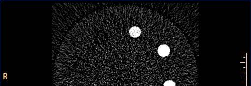
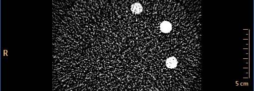
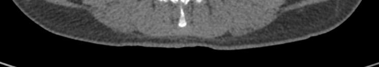
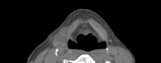
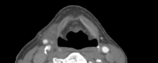
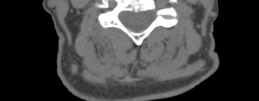
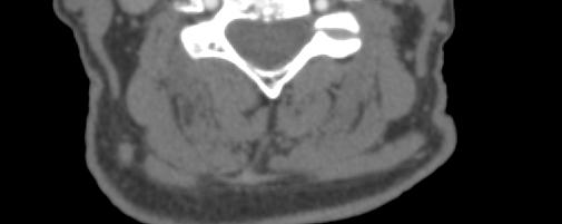
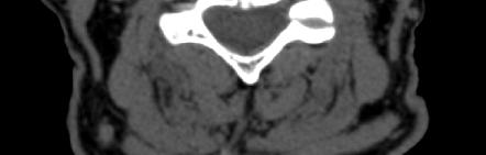
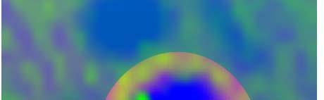
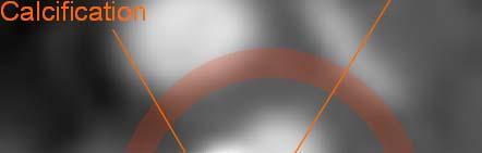
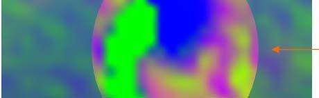
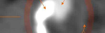
14 Clinical Images, Obtained with A Dual-Layer Detector Spectral CT 1. A Philips Brilliance-64 with a Double-Layer Detector operates routinely in Hadassah Medical Center, at the Hebrew University in Jerusalem. 2. Dual Energy scans are performed at 140 kvp with conventional dose, 250 mas for all protocols 3. All images are courtesy of Hadassah MC, and Dr. Jacob Sosna, Head of the CT unit there. 140 kv 250 mas Separation line HU of E1 H 2 O Iodine Calcium HU of E2 1. Iodine-tagged blood well separated from blood-vessel calcifications and bones 2. Soft-tissue (muscles) are well separated even from lowconcentrated Iodine regions 3. Different materials / tissues are overlayed with colors on the anatomic image Soft tissue separation from Iodine contrast and from bones: Soft Tissue Iodine-tagged Blood Spectral Analysis Map Calcium & Bones Fat HU of E1 Iodine Calcium Conventional CT Image Spectral CT Image, Dual-E Soft tissue HU of E2 14


15 Virtual Non Contrast Image Generation (for algorithms & methods see L. Goshen, A. Altman & R. Crami MIC2008 IEEE) 250 mas 250 mas 15


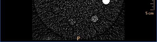
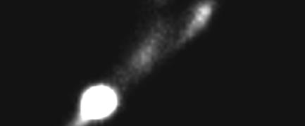
, obtained with a PHILIPS Dual-Energy CT Note")
, the Lung- Nodule looks as a normal")

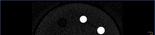
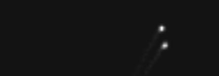
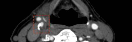
16 Dual Energy Images Advanced Iodine Perfusion Maps, Tissues/Material Decomposition Main Procedure: 1800 Noise Level Estimate Raw energy map 1800 Noise Removal, preserving Spectral Map information Noise free energy map Estimate of Material Response Vector Iodine Map Generation Iodine Color Map A tiny lung nodule detected on an Iodine-map image a b (b), obtained with a PHILIPS Dual-Energy CT Note that on the conventional CT Image (obtained simultaneously during the same scan), the Lung- Nodule looks as a normal Iodine-Tagged d blood vessel Conventional CT Spectral Iodine Maps Conventional CT Iodine Image A detected non-perfused Lung Nodule (Tumor) 16


17 Towards Prepless CT Colonoscopy with Dual-Energy CT Nominal Virtual-Colonoscopy scan protocol and dose a b The colon is partially filled with stool and both thiodine and Barium contrast agents c d Corrupted colon wall Non-cleansed residuals Electronic cleansing with dual-energy analysis Conventional-CT electronic cleansing with high and low HU thresholds only 11 17
18 Towards Prepless CT Colonoscopy with Dual-Energy CT (cont.) Compare Mode Conventional Electronic Cleansing Dual Energy Electronic Cleansing Bowel is still full of stool 18
19 Towards Prepless CT Colonoscopy with Dual-Energy CT (cont.) Conventional Electronic Cleansing Dual Energy Electronic Cleansing A false polyp caused by residual stool 19

20 Quantifying Composites of Tissues Mixtures, Soft-Plaque Characterization Vulnerable Plaque in Carotids Purple indicates high lipidic component in plaque Calcification Lumen Soft Plaque 20

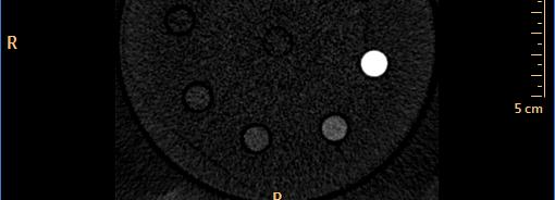
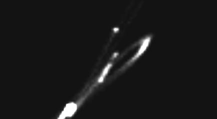
21 Kidneys Stones Identification and Quantification + Brushite + + Calcium Oxalate monohydrated = Brushite Cystine + Urique acid Uric Acid In-Vivo Kidneys Stone analysis, using a Calibration Phantom 21
22 Simultaneous Multi-Phase Imaging Using Contrast Agents Mix, injected in Separate times 1. Plaque-induced NWZ Rabbits, through cholesterol-rich diet 2. Early injection of targeted Iodine-Loaded nano-particles contrast agent, highly up-taken by Macrophages (N1177 NPC, developed and manufactured by NanoScan Imaging, g, Lansdale, PA) 3. Late injection (hours) of Gd Contrast-Agent (Magnevist 280) 4. Scanning to image simultaneously both plaque and lumen 22
 N1177 (iodine) + gadolinium.")
 Material separation with dual-energy spectral analysis")


23 Demonstrating Material separation: Iodine vs. bone + gadolinium A) N1177 (iodine) + gadolinium. Scan: 4 hours after N1177 injection and immediately after gadolinium injection B) Material separation with dual-energy spectral analysis shows the differentiation between iodine to gadolinium and bone A B bone and gadolinium iodine Gadolinium contrast material in the heart Gadolinium contrast material in the heart Iodine nanoparticles contrast material in the spleen Iodine nanoparticles contrast material in the spleen Note that the spleen is rich with Macrophages! 23

 N1177")
 Material separation with")


24 A) N1177 (iodine nanoparticles) Scan: 2 hours after injection A A first example showing possible plaque in the aorta B) N1177 (iodine) + gadolinium. C) Material separation with dual-energy Scan:4 hours after N1177 spectralanalysis analysis shows the differentiation injection and immediately between iodine in the soft plaque and after gadolinium injection gadolinium in the aorta lumen B C 139 HU Iodine nanoparticles captured in soft plaque. Max. intensity after 2 h, reducing after 4 h soft plaque (iodine) Gadolinium enhancement of the aorta lumen - can help in areas where the lumen walls are less clear 122 HU 134 HU gadolinium bone and gadolinium iodine 24
 Scan: 2 hours after injection A B) N1177 (iodine) + gadolinium.")


25 A Second Example, Soft-Plaque Imaging Simultaneously with The Lumen A) N1177 (iodine nanoparticles) Scan: 2 hours after injection A B) N1177 (iodine) + gadolinium. C) Material separation with dual-energy Scan: 4 hours after N1177 spectral analysis shows the differentiation injection and immediately between iodine to gadolinium and bone after gadolinium injection B C Possibly some captured iodine inside plaque in the aorta walls bone bone bone and gadolinium iodine iodine nanoparticles concentrated in the spleen iodine nanoparticles concentrated in the spleen Possibly some captured iodine inside plaque in the aorta walls and gadolinium enhancement of the aorta lumen probably: plaque / lumen (iodine / gadolinium) differentiation 25 25


26 Philips Healthcare,
Data Acquisition and Image Formation Methods for Multi Energy CT
 Data Acquisition and Image Formation Methods for Multi Energy CT Cynthia H. McCollough, PhD, DABR, FAIMBE, FAAPM, FACR Professor of Medical Physics and Biomedical Engineering Director, CT Clinical Innovation
Multi-Energy CT: Principles, Processing
 Multi-Energy CT: Principles, Processing and Clinical Applications Shuai Leng, PhD Associate Professor Department of Radiology Mayo Clinic, Rochester, MN Clinical Motivation CT number depends on x-ray attenuation
Applications of Low KeV Imaging in Abdomen
 Applications of Low KeV Imaging in Abdomen Dushyant Sahani, M.D Director of CT Associate Professor of Radiology Massachusetts General Hospital Harvard Medical School Email-dsahani@partners.org Disclosure
A practical approach to the introduction of spectral imaging into a large UK acute care teaching hospital
 A practical approach to the introduction of spectral imaging into a large UK acute care teaching hospital Robert Loader Clinical Scientist Clinical & Radiation Physics Directorate of Healthcare Science
Metal Artifact Reduction and Dose Efficiency Improvement on Photon Counting Detector CT using an Additional Tin Filter
 Metal Artifact Reduction and Dose Efficiency Improvement on Photon Counting Detector CT using an Additional Tin Filter Wei Zhou, Dilbar Abdurakhimova, Kishore Rajendran, Cynthia McCollough, Shuai Leng
Two-Material Decomposition From a Single CT Scan Using Statistical Image Reconstruction
 / 5 Two-Material Decomposition From a Single CT Scan Using Statistical Image Reconstruction Yong Long and Jeffrey A. Fessler EECS Department James M. Balter Radiation Oncology Department The University
Multi-energy CT: Future Directions. Acknowledgements. Overview 7/23/2014. Taly Gilat Schmidt, PhD. Kevin Zimmerman Franco Rupcich Steven Haworth
 Multi-energy CT: Future Directions Taly Gilat Schmidt, PhD Department of Biomedical Engineering Marquette University Acknowledgements Kevin Zimmerman Franco Rupcich Steven Haworth Results in this talk:
Metal Artifact Reduction with DECT
 Metal Artifact Reduction with DECT Daniele Marin, MD Duke University Medical Center Metal artifacts Common clinical problem ( 20%) Boas EF et al. Radiology 2011 Beam Hardening Edge Effects Scatter Metal
Rad T 290 Worksheet 2
 Class: Date: Rad T 290 Worksheet 2 1. Projectile electrons travel from a. anode to cathode. c. target to patient. b. cathode to anode. d. inner shell to outer shell. 2. At the target, the projectile electrons
Initial Studies in Proton Computed Tomography
 SCIPP Initial Studies in Proton Computed Tomography L. R. Johnson, B. Keeney, G. Ross, H. F.-W. Sadrozinski, A. Seiden, D.C. Williams, L. Zhang Santa Cruz Institute for Particle Physics, UC Santa Cruz,
X. Allen Li. Disclosure. DECT: What, how and Why Why dual-energy CT (DECT)? 7/30/2018. Improving delineation and response assessment using DECT in RT
? 7/30/2018. Improving delineation and response assessment using DECT in RT") Improving delineation and response assessment using DECT in RT X. Allen Li Medical College of Wisconsin MO-A-DBRA-1, AAPM, July 30 th, 2018 Disclosure Research funding support: Siemens Healthineers Elekta
Improving delineation and response assessment using DECT in RT X. Allen Li Medical College of Wisconsin MO-A-DBRA-1, AAPM, July 30 th, 2018 Disclosure Research funding support: Siemens Healthineers Elekta
Carlo N. De Cecco, MD, PhD
 New Contrast Injection Strategies in Low kv and kev Imaging Carlo N. De Cecco, MD, PhD FSCBTMR - FSCCT - FESGAR Consultant for / Research support from: Siemens Bayer Guerbet Low kv and kev imaging Rationale
Towards Proton Computed Tomography
 SCIPP Towards Proton Computed Tomography L. R. Johnson, B. Keeney, G. Ross, H. F.-W. Sadrozinski, A. Seiden, D.C. Williams, L. Zhang Santa Cruz Institute for Particle Physics, UC Santa Cruz, CA 95064 V.
CT-PET calibration : physical principles and operating procedures F.Bonutti. Faustino Bonutti Ph.D. Medical Physics, Udine University Hospital.
 CT-PET calibration : physical principles and operating procedures Faustino Bonutti Ph.D. Medical Physics, Udine University Hospital Topics Introduction to PET physics F-18 production β + decay and annichilation
1-D Fourier Transform Pairs
 1-D Fourier Transform Pairs The concept of the PSF is most easily explained by considering a very small point source being placed in the imaging field-of-view The relationship between the image, I, and
Radionuclide Imaging MII Positron Emission Tomography (PET)
") Radionuclide Imaging MII 3073 Positron Emission Tomography (PET) Positron (β + ) emission Positron is an electron with positive charge. Positron-emitting radionuclides are most commonly produced in cyclotron
Radionuclide Imaging MII 3073 Positron Emission Tomography (PET) Positron (β + ) emission Positron is an electron with positive charge. Positron-emitting radionuclides are most commonly produced in cyclotron
1. Which of the following statements is true about Bremsstrahlung and Characteristic Radiation?
 BioE 1330 - Review Chapters 4, 5, and 6 (X-ray and CT) 9/27/2018 Instructions: On the Answer Sheet, enter your 2-digit ID number (with a leading 0 if needed) in the boxes of the ID section. Fill in the
Introduction to SPECT & PET TBMI02 - Medical Image Analysis 2017
 Introduction to SPECT & PET TBMI02 - Medical Image Analysis 2017 Marcus Ressner, PhD, Medical Radiation Physicist, Linköping University Hospital Content What is Nuclear medicine? Basic principles of Functional
X-ray Interaction with Matter
 X-ray Interaction with Matter 10-526-197 Rhodes Module 2 Interaction with Matter kv & mas Peak kilovoltage (kvp) controls Quality, or penetrating power, Limited effects on quantity or number of photons
Electron density and effective atomic number images generated by dual energy imaging with a 320-detector CT system: A feasibility study
 Electron density and effective atomic number images generated by dual energy imaging with a 320-detector CT system: A feasibility study Poster No.: C-0403 Congress: ECR 2014 Type: Scientific Exhibit Authors:
Physics 210 Medical Physics Midterm Exam Winter 2015 February 13, 2015
 Physics 210 Medical Physics Midterm Exam Winter 2015 February 13, 2015 Name Problem 1 /24 Problem 2 /24 Problem 3 /24 Total /76 I affirm that I have carried out my academic endeavors with full academic
31545 Medical Imaging systems
 Simulation of ultrasound systems and non-linear imaging 545 Medical Imaging systems Lecture 9: Simulation of ultrasound systems and non-linear imaging Jørgen Arendt Jensen Department of Electrical Engineering
Abdominal DECT: How to Integrate Into Your Practice
 Abdominal DECT: How to Integrate Into Your Practice Eric Tamm, M.D. Department of Diagnostic Radiology Division of Diagnostic Imaging MD Anderson Cancer Center Houston, TX Disclosure I have no relationships
Part III Minor Option in Medical Physics 2018 Examples Sheet
 Part III Minor Option in Medical Physics 2018 Examples Sheet Any errors or comments should be addressed sent to: seb53@cam.ac.uk URLs that may be useful: Stanford Event Generation Simulator: http://tinyurl.com/pkg476r
Application of Nuclear Physics
 Application of Nuclear Physics Frontier of gamma-ray spectroscopy 0.1 IR visible light UV soft X-ray X-ray hard X-ray gamma-ray 1 10 100 1e3 1e4 1e5 1e6 energy [ev] Photoelectric effect e - Compton scattering
New perspectives in X-ray detection of concealed illicit materials brought by CdTe/CdZnTe spectrometric detectors
 New perspectives in X-ray detection of concealed illicit materials brought by CdTe/CdZnTe spectrometric detectors Jean-Marc Dinten, Jean-Louis Amans, Loïck Verger, Olivier Peyret CEA-LETI, MINATEC, Recherche
DUAL ENERGY of the Pancreas
 DUAL ENERGY of the Pancreas Desiree E. Morgan, MD Professor and Vice Chair Clinical Research Director Human Imaging Shared Facility UAB CCC University of Alabama at Birmingham Opportunities to improve?
The physics of medical imaging US, CT, MRI. Prof. Peter Bogner
 The physics of medical imaging US, CT, MRI Prof. Peter Bogner Clinical radiology curriculum blocks of lectures and clinical practice (7x2) Physics of medical imaging Neuroradiology Head and neck I. Head
Differential Absorption Analysis of Nonmagnetic Material in the Phantom using Dual CT
 Journal of Magnetics 21(2), 286-292 (2016) ISSN (Print) 1226-1750 ISSN (Online) 2233-6656 http://dx.doi.org/10.4283/jmag.2016.21.2.286 Differential Absorption Analysis of Nonmagnetic Material in the Phantom
Neural Network Approach for Photon-counting Detection The First Step: PPE Correction
 Neural Network Approach for Photon-counting Detection The First Step: PPE Correction Ruibin Feng, Ph.D. Biomedical Imaging Center, CBIS/BME, RPI fengr@rpi.edu David Rundle JairiNovus Technologies Ltd.
Midterm Review. Yao Wang Polytechnic University, Brooklyn, NY 11201
 Midterm Review Yao Wang Polytechnic University, Brooklyn, NY 11201 Based on J. L. Prince and J. M. Links, Medical maging Signals and Systems, and lecture notes by Prince. Figures are from the textbook.
Investigation of Uncertainty Sources in the Determination of Gamma Emitting Radionuclides in the WBC
 Investigation of Uncertainty Sources in the Determination of Gamma Emitting Radionuclides in the WBC A. Specification Whole body counting method is used to detect the gamma rays emitted by radio nuclides,
MEDICAL IMAGING. METHODS OF MODERN IMAGING, BASED ON ELECTRO-MAGNETIC RADIATION (radiowaves, infrared radiation, X-rays, γ-rays ) AND ULTRASOUND
 AND ULTRASOUND") MEDICAL IMAGING MEDICAL IMAGING METHODS OF MODERN IMAGING, BASED ON ELECTRO-MAGNETIC RADIATION (radiowaves, infrared radiation, X-rays, γ-rays ) AND ULTRASOUND MEDICAL IMAGING RADIOLOGY NUCLEAR MEDICINE
MEDICAL IMAGING MEDICAL IMAGING METHODS OF MODERN IMAGING, BASED ON ELECTRO-MAGNETIC RADIATION (radiowaves, infrared radiation, X-rays, γ-rays ) AND ULTRASOUND MEDICAL IMAGING RADIOLOGY NUCLEAR MEDICINE
Radiation Detection and Measurement
 Radiation Detection and Measurement June 2008 Tom Lewellen Tkldog@u.washington.edu Types of radiation relevant to Nuclear Medicine Particle Symbol Mass (MeV/c 2 ) Charge Electron e-,! - 0.511-1 Positron
EE 5345 Biomedical Instrumentation Lecture 6: slides
 EE 5345 Biomedical Instrumentation Lecture 6: slides 129-147 Carlos E. Davila, Electrical Engineering Dept. Southern Methodist University slides can be viewed at: http:// www.seas.smu.edu/~cd/ee5345.html
Fast and compact proton radiography imaging system for proton radiotherapy
 Fast and compact proton radiography imaging system for proton radiotherapy Aleksandra K. Biegun ATTRACT NL Kick-off event, 9 th February 2017, Amsterdam, The Netherlands Proton therapy work flow CT scan
SURROGATE REACTIONS. An overview of papers by Jason Burke from LLNL
 SURROGATE REACTIONS An overview of papers by Jason Burke from LLNL Compound Nuclear Reaction cross sections Cross sections for compound-nuclear reactions are required input for astrophysical models and
Chapter 30 X Rays GOALS. When you have mastered the material in this chapter, you will be able to:
 Chapter 30 X Rays GOALS When you have mastered the material in this chapter, you will be able to: Definitions Define each of the following terms, and use it in an operational definition: hard and soft
Topics. EM spectrum. X-Rays Computed Tomography Direct Inverse and Iterative Inverse Backprojection Projection Theorem Filtered Backprojection
 Bioengineering 28A Principles of Biomedical Imaging Fall Quarter 25 X-Rays/CT Lecture Topics X-Rays Computed Tomography Direct Inverse and Iterative Inverse Backprojection Projection Theorem Filtered Backprojection
A Brief Introduction to Medical Imaging. Outline
 A Brief Introduction to Medical Imaging Outline General Goals Linear Imaging Systems An Example, The Pin Hole Camera Radiations and Their Interactions with Matter Coherent vs. Incoherent Imaging Length
ESTIMATION OF 90 SCATTERING COEFFICIENT IN THE SHIELDING CALCULATION OF DIAGNOSTIC X-RAY EQUIPMENT
 Proceedings of the Eleventh EGS4 Users' Meeting in Japan, KEK Proceedings 2003-15, p.107-113 ESTIMATION OF 90 SCATTERING COEFFICIENT IN THE SHIELDING CALCULATION OF DIAGNOSTIC X-RAY EQUIPMENT K. Noto and
Potentials for Dual-energy kv/mv On-board Imaging and Therapeutic Applications
 Potentials for Dual-energy kv/mv On-board Imaging and Therapeutic Applications Fang-Fang Yin Department of Radiation Oncology Duke University Medical Center Acknowledgement Dr Hao Li for his excellent
Topics. EM spectrum. X-Rays Computed Tomography Direct Inverse and Iterative Inverse Backprojection Projection Theorem Filtered Backprojection
 Bioengineering 28A Principles of Biomedical Imaging Fall Quarter 24 X-Rays/CT Lecture Topics X-Rays Computed Tomography Direct Inverse and Iterative Inverse Backprojection Projection Theorem Filtered Backprojection
Bioengineering 280A Principles of Biomedical Imaging. Fall Quarter 2005 X-Rays/CT Lecture 1. Topics
 Bioengineering 28A Principles of Biomedical Imaging Fall Quarter 25 X-Rays/CT Lecture Topics X-Rays Computed Tomography Direct Inverse and Iterative Inverse Backprojection Projection Theorem Filtered Backprojection
arxiv: v1 [physics.ins-det] 29 Jun 2011
![arxiv: v1 [physics.ins-det] 29 Jun 2011](/thumbs/74/71147369.jpg "arxiv: v1 [physics.ins-det] 29 Jun 2011") Investigation of Large LGB Detectors for Antineutrino Detection P. Nelson a,, N. S. Bowden b, a Department of Physics, Naval Postgraduate School, Monterey, CA 99, USA b Lawrence Livermore National Laboratory,
Investigation of Large LGB Detectors for Antineutrino Detection P. Nelson a,, N. S. Bowden b, a Department of Physics, Naval Postgraduate School, Monterey, CA 99, USA b Lawrence Livermore National Laboratory,
Outline Chapter 14 Nuclear Medicine
 Outline Chapter 14 uclear Medicine Radiation Dosimetry I Text: H.E Johns and J.R. Cunningham, The physics of radiology, 4 th ed. http://www.utoledo.edu/med/depts/radther Introduction Detectors for nuclear
CHAPTER 4 RADIATION ATTENUATION
 HDR202 PHYSICS FOR RADIOGRAPHERS 2 CHAPTER 4 RADIATION ATTENUATION PREPARED BY: MR KAMARUL AMIN BIN ABDULLAH SCHOOL OF MEDICAL IMAGING FACULTY OF HEALTH SCIENCES Learning Objectives At the end of the lesson,
How we wanted to revolutionize X-ray radiography, and how we then "accidentally" discovered single-photon CMOS imaging
 How we wanted to revolutionize X-ray radiography, and how we then "accidentally" discovered single-photon CMOS imaging Stanford University EE Computer Systems Colloquium February 23 rd, 2011 EE380 Peter
The relationship between image noise and spatial resolution of CT scanners
 The relationship between image noise and spatial resolution of CT scanners Sue Edyvean, Nicholas Keat, Maria Lewis, Julia Barrett, Salem Sassi, David Platten ImPACT*, St George s Hospital, London *An MDA
AQA Physics /7408
 AQA Physics - 7407/7408 Module 10: Medical physics You should be able to demonstrate and show your understanding of: 10.1 Physics of the eye 10.1.1 Physics of vision The eye as an optical refracting system,
Prompt gamma measurements for the verification of dose deposition in proton therapy. Contents. Two Proton Beam Facilities for Therapy and Research
 Prompt gamma measurements for the verification of dose deposition in proton therapy Two Proton Beam Facilities for Therapy and Research Ion Beam Facilities in Korea 1. Proton therapy facility at National
FXA UNIT G485 Module X-Rays. Candidates should be able to : I = I 0 e -μx
 1 Candidates should be able to : HISTORY Describe the nature of X-rays. Describe in simple terms how X-rays are produced. X-rays were discovered by Wilhelm Röntgen in 1865, when he found that a fluorescent
Nuclear Medicine Intro & Physics from Medical Imaging Signals and Systems, Chapter 7, by Prince and Links
 Nuclear Medicine Intro & Physics from Medical Imaging Signals and Systems, Chapter 7, by Prince and Links NM - introduction Relies on EMISSION of photons from body (versus transmission of photons through
Chapter 2 PET Imaging Basics
 Chapter 2 PET Imaging Basics Timothy G. Turkington PET Radiotracers Positron emission tomography (PET) imaging is the injection (or inhalation) of a substance containing a positron emitter, the subsequent
Bases of radioisotope diagnostic methods
 Medical, pharmaceutical applications of radioisotopes Bases of radioisotope diagnostic methods Dr. István Voszka Basis of application: radioisotopes have identical behavior in the organism to corresponding
Mayneord-Phillips Summer School St Edmund Hall, University of Oxford July Proton decays to n, e +, ν
 Positron Emission Tomography Physics & Instrumentation Dimitra G. Darambara, Ph.D Multimodality Molecular Imaging Joint Department of Physics RMH/ICR Outline Introduction PET Physics overview Types of
IBIS - IN FLIGHT CALIBRATION ACTIVITIES
 IBIS - IN FLIGHT CALIBRATION ACTIVITIES Natalucci on behalf of the IBIS Team INTEGRAL/IBIS Calibration Update THE IBIS INSTRUMENT coded mask, placed 3.2m above detector (1m2) Collection area ~ 3000 cm2
Biomedical Imaging. X ray imaging. Patrícia Figueiredo IST
 Biomedical Imaging X ray imaging Patrícia Figueiredo IST 2013-2014 Overview Production of X rays Interaction of electrons with matter X ray spectrum X ray tube Interaction of X rays with matter Photoelectric
DEVIL PHYSICS THE BADDEST CLASS ON CAMPUS IB PHYSICS
 DEVIL PHYSICS THE BADDEST CLASS ON CAMPUS IB PHYSICS TSOKOS OPTION I-2 MEDICAL IMAGING Reading Activity Answers IB Assessment Statements Option I-2, Medical Imaging: X-Rays I.2.1. I.2.2. I.2.3. Define
October 4th, Bioengineering 508: Physical Aspects of Medical Imaging Some Elementary Particles
 Bioengineering 508: Physical Aspects of Medical Imaging http://courses.washington.edu/bioen508/ For questions, remarks, discussions, errors in the book: Class Discussion Board (link from class website)
Technical University of Denmark
 Technical University of Denmark Page 1 of 11 pages Written test, 9 December 2010 Course name: Introduction to medical imaging Course no. 31540 Aids allowed: none. "Weighting": All problems weight equally.
Radionuclide Imaging MII Detection of Nuclear Emission
 Radionuclide Imaging MII 3073 Detection of Nuclear Emission Nuclear radiation detectors Detectors that are commonly used in nuclear medicine: 1. Gas-filled detectors 2. Scintillation detectors 3. Semiconductor
The Physics of PET/CT scanners
 The Physics of PET/CT scanners Ruth E. Schmitz, Adam M. Alessio, and Paul E. Kinahan Imaging Research Laboratory Department of Radiology University of Washington What Makes PET Useful? Positron emission
BNG/ECE 487 FINAL (W16)
") BNG/ECE 487 FINAL (W16) NAME: 4 Problems for 100 pts This exam is closed-everything (no notes, books, etc.). Calculators are permitted. Possibly useful formulas and tables are provided on this page. Fourier
BNG/ECE 487 FINAL (W16) NAME: 4 Problems for 100 pts This exam is closed-everything (no notes, books, etc.). Calculators are permitted. Possibly useful formulas and tables are provided on this page. Fourier
University of Cyprus. Reflectance and Diffuse Spectroscopy
 University of Cyprus Biomedical Imaging and Applied Optics Reflectance and Diffuse Spectroscopy Spectroscopy What is it? from the Greek: spectro = color + scope = look at or observe = measuring/recording
Time-of-Flight PET using Cherenkov Photons Produced in PbF 2
 Photons Produced in PbF 2 R. Dolenec a, S. Korpar b,a, P. Križan c,a, R. Pestotnik a, A. Stanovnik d,a a, Ljubljana, Slovenia b Faculty of Chemistry and Chemical Engineering, University of Maribor, Slovenia
Detecting high energy photons. Interactions of photons with matter Properties of detectors (with examples)
") Detecting high energy photons Interactions of photons with matter Properties of detectors (with examples) Interactions of high energy photons with matter Cross section/attenution length/optical depth Photoelectric
Detecting high energy photons Interactions of photons with matter Properties of detectors (with examples) Interactions of high energy photons with matter Cross section/attenution length/optical depth Photoelectric
Prospects for achieving < 100 ps FWHM coincidence resolving time in time-of-flight PET
 Prospects for achieving < 100 ps FWHM coincidence resolving time in time-of-flight PET, 28-Feb-2012, ICTR-PHE, Geneva, Switzerland 1 Time-of-flight PET Colon cancer, left upper quadrant peritoneal node
The GEM scintillation in He-CF 4, Ar-CF 4, Ar-TEA and Xe-TEA mixtures
 The GEM scintillation in He-CF 4, Ar-CF 4, Ar-TEA and Xe-TEA mixtures M. M. Fraga, F. A. F. Fraga, S. T. G. Fetal, L. M. S. Margato, R. Ferreira Marques and A. J. P. L. Policarpo LIP- Coimbra, Dep. Física,
The WBS CCDs as cosmic ray detectors. V. Ossenkopf, KOSMA
 The WBS CCDs as cosmic ray detectors V. Ossenkopf, KOSMA, 26-30th March, 2012 WBS design WBS is an acusto-optical spectrometer Involves CCD to detect laser light Always also susceptible to any other radiation
A small object is placed a distance 2.0 cm from a thin convex lens. The focal length of the lens is 5.0 cm.
 TC [66 marks] This question is about a converging (convex) lens. A small object is placed a distance 2.0 cm from a thin convex lens. The focal length of the lens is 5.0 cm. (i) Deduce the magnification
Figure 1: FAST beamline (1).
.") Channeling Radiation Experiment: Calibration of X-ray Detector and Measurement of Emittance of Electron Beam K. G. Capobianco-Hogan Introduction Current x-ray production methods utilize large synchrotron
Channeling Radiation Experiment: Calibration of X-ray Detector and Measurement of Emittance of Electron Beam K. G. Capobianco-Hogan Introduction Current x-ray production methods utilize large synchrotron
Production of X-rays. Radiation Safety Training for Analytical X-Ray Devices Module 9
 Module 9 This module presents information on what X-rays are and how they are produced. Introduction Module 9, Page 2 X-rays are a type of electromagnetic radiation. Other types of electromagnetic radiation
Basic physics Questions
 Chapter1 Basic physics Questions S. Ilyas 1. Which of the following statements regarding protons are correct? a. They have a negative charge b. They are equal to the number of electrons in a non-ionized
UV-Vis optical fiber assisted spectroscopy in thin films and solutions
 UV-Vis optical fiber assisted spectroscopy in thin films and solutions Description UV-Visible absorption and transmission spectra provide fundamental information for all experiments related to the attenuation
ISPA-Tubes with YAP:Ce Active Windows for X and Gamma Ray Imaging.
 PIXEL 2000 International Workshop on Semiconductor Pixel Detectors for Particles and X-Rays Genova - Porto Antico - Magazzini del Cotone (Sala Libeccio) June 5-8, 2000 ISPA-Tubes with YAP:Ce Active Windows
3. Which of the following statements is (are) TRUE about detector crystals in Anger cameras?
 TRUE about detector crystals in Anger cameras?") BioE 1330 - Exam 2 11/13/2018 Answer Sheet - Correct answer is A for all questions 1. Unlike CT, in nuclear medicine A. Bremsstrahlung is not used to produce high-energy photons. B. signal can be increased
BioE 1330 - Exam 2 11/13/2018 Answer Sheet - Correct answer is A for all questions 1. Unlike CT, in nuclear medicine A. Bremsstrahlung is not used to produce high-energy photons. B. signal can be increased
I. Image Acquisition Physics and Hardware
 CT System Course (SAM) I. Image Acquisition Physics and Hardware Baojun Li, PhD Department of Radiology Medical Center 1 Acknowledgement No conflict of interest to disclose Rolf Behling, Philips Healthcare
ROSAT Roentgen Satellite. Chandra X-ray Observatory
 ROSAT Roentgen Satellite Joint facility: US, Germany, UK Operated 1990 1999 All-sky survey + pointed observations Chandra X-ray Observatory US Mission Operating 1999 present Pointed observations How do
Design and Development of a Smartphone Based Visible Spectrophotometer for Analytical Applications
 Design and Development of a Smartphone Based Visible Spectrophotometer for Analytical Applications Bedanta Kr. Deka, D. Thakuria, H. Bora and S. Banerjee # Department of Physicis, B. Borooah College, Ulubari,
Radiation Detectors. How do we detect ionizing radiation? What are these effects? Types of Ionizing Radiation Detectors
 Radiation Detectors 1 How do we detect ionizing radiation? Indirectly, by its effects as it traverses matter? What are these effects? Ionization and excitation of the atoms and molecules Heat 2 Types of
MEDICAL EQUIPMENT: NUCLEAR MEDICINE. Prof. Yasser Mostafa Kadah
 MEDICAL EQUIPMENT: NUCLEAR MEDICINE Prof. Yasser Mostafa Kadah www.k-space.org Recommended Textbook Introduction to Medical Imaging: Physics, Engineering and Clinical Applications, by Nadine Barrie Smith
Detection of X-Rays. Solid state detectors Proportional counters Microcalorimeters Detector characteristics
 Detection of X-Rays Solid state detectors Proportional counters Microcalorimeters Detector characteristics Solid State X-ray Detectors X-ray interacts in material to produce photoelectrons which are collected
Procesamiento de Imágenes y Bioseñales
 Procesamiento de Imágenes y Bioseñales Dr. Víctor Castañeda Agenda Physical basis of X-ray- CT, NMR, Ultrasound, Nuclear Medicine Sensors (cameras, gamma probes, microphone) Computational Tomography (CT)
What is scintigraphy? The process of obtaining an image or series of sequential images of the distribution of a radionuclide in tissues, organs, or
 Let's remind... What is nuclear medicine? Nuclear medicine can be broadly divided into two branches "in vitro" and "in vivo" procedures. There are numerous radioisotopic "in vitro" procedures for genotyping
MASS SPECTROMETRY. Topics
 MASS SPECTROMETRY MALDI-TOF AND ESI-MS Topics Principle of Mass Spectrometry MALDI-TOF Determination of Mw of Proteins Structural Information by MS: Primary Sequence of a Protein 1 A. Principles Ionization:
Cambridge University Press MRI from A to Z: A Definitive Guide for Medical Professionals Gary Liney Excerpt More information
 Main glossary Aa AB systems Referring to molecules exhibiting multiply split MRS peaks due to spin-spin interactions. In an AB system, the chemical shift between the spins is of similar magnitude to the
Developments & Limitations in GSR Analysis
 Developments & Limitations in GSR Analysis ENFSI Working Group Meeting June 2006 Jenny Goulden Oxford Instruments NanoAnalysis Overview Introduction Developments in GSR Software Importance of EDS Hardware
Evaluation of Phantom Equivalent Materials in Polychromatic Diagnostic X-Ray Beam
 Evaluation of Phantom Equivalent Materials in Polychromatic Diagnostic X-Ray Beam Radhakrishnan B Nair 1*, Ramakrishnan G 2, Chandralingam S 3 and Kurup PGG 1 1 Apollo Speciality Hospital, Chennai, India
Development of a Dedicated Hard X-Ray Polarimeter Mark L. McConnell, James R. Ledoux, John R. Macri, and James M. Ryan
 Development of a Dedicated Hard X-Ray Polarimeter Mark L. McConnell, James R. Ledoux, John R. Macri, and James M. Ryan Space Science Center University of New Hampshire Durham, NH AAS-HEAD Mt. Tremblant,
The Theory of HPLC. Quantitative and Qualitative HPLC
 The Theory of HPLC Quantitative and Qualitative HPLC i Wherever you see this symbol, it is important to access the on-line course as there is interactive material that cannot be fully shown in this reference
Expand the probe idea functionality (above points) to larger imaging systems. First Applications, Probes, Isotopes
 to larger imaging systems. First Applications, Probes, Isotopes") Gamma Ray and Beta Ray Probes Larry MacDonald Imaging Research Laboratory University of Washington Radiology http://depts.washington.edu/nucmed/irl/ 23 Oct. 2007 Oct. 2007 1 Gamma Ray and Beta Ray Probes
Gamma Ray and Beta Ray Probes Larry MacDonald Imaging Research Laboratory University of Washington Radiology http://depts.washington.edu/nucmed/irl/ 23 Oct. 2007 Oct. 2007 1 Gamma Ray and Beta Ray Probes
Characteristics and Structure of Matter Perry Sprawls, Ph.D.
 Online Textbook Perry Sprawls, Ph.D. Table of Contents INTRODUCTION AND OVERVIEW NUCLEAR STRUCTURE Composition Nuclides Isotopes Isobars Isomers Isotones NUCLEAR STABILITY Radioactivity NUCLEAR ENERGY
Nuclear Lifetimes. = (Eq. 1) (Eq. 2)
 (Eq. 2)") Nuclear Lifetimes Theory The measurement of the lifetimes of excited nuclear states constitutes an important experimental technique in nuclear physics. The lifetime of a nuclear state is related to its
Nuclear Lifetimes Theory The measurement of the lifetimes of excited nuclear states constitutes an important experimental technique in nuclear physics. The lifetime of a nuclear state is related to its
International Journal of Scientific & Engineering Research, Volume 5, Issue 3, March-2014 ISSN
 316 Effective atomic number of composite materials by Compton scattering - nondestructive evaluation method Kiran K U a, Ravindraswami K b, Eshwarappa K M a and Somashekarappa H M c* a Government Science
Reconstruction for Proton Computed Tomography: A Monte Carlo Study
 Reconstruction for Proton Computed Tomography: A Monte Carlo Study T Li, Z. Liang, K. Mueller, J. Heimann, L. Johnson, H. Sadrozinski, A. Seiden, D. Williams, L. Zhang, S. Peggs, T. Satogata, V. Bashkirov,
The Imaging Chain for X-Ray Astronomy
 The Imaging Chain for X-Ray Astronomy Pop quiz (1): Which is the X-ray Image? B. A. Answer: B!!! (But You Knew That) Pop quiz (2): Which of These is the X-Ray Image? A. B. C. B. A. The dying star ( planetary
Nuclear Physics and Astrophysics
 Nuclear Physics and Astrophysics PHY-302 Dr. E. Rizvi Lecture 24 Medical Imaging Effects of Radiation We now know what radiation is But what does it mean for our bodies? Radioactivity is quantified in
Tests of the BURLE 64-anode MCP PMT as the detector of Cherenkov photons
 Tests of the BURLE 64-anode MCP PMT as the detector of Cherenkov photons Peter Križan University of Ljubljana and J. Stefan Institute Contents Motivation and requirements BURLE MCP-PMT Beam test results
Shielding Design for the Imaging and Medical Beamline at the Australian Synchrotron
 Shielding Design for the Imaging and Medical Beamline at the Australian Synchrotron P. Berkvens and D. Häusermann European Synchrotron Radiation Facility BP 0, Grenoble Cedex 0, France Australian Synchrotron