University of Alberta
|
|
|
- Evangeline Hopkins
- 5 years ago
- Views:
Transcription
1 University of Alberta One-step fabrication of crystalline TiO 2 nanotubualr arrays and relevant temperature influences by Jie Zhang A thesis submitted to the Faculty of Graduate Studies and Research in partial fulfillment of the requirements for the degree of Master of Science in Materials Engineering Department of Chemical and Materials Engineering Jie Zhang Spring 2012 Edmonton, Alberta Permission is hereby granted to the University of Alberta Libraries to reproduce single copies of this thesis and to lend or sell such copies for private, scholarly or scientific research purposes only. Where the thesis is converted to, or otherwise made available in digital form, the University of Alberta will advise potential users of the thesis of these terms. The author reserves all other publication and other rights in association with the copyright in the thesis and, except as herein before provided, neither the thesis nor any substantial portion thereof may be printed or otherwise reproduced in any material form whatsoever without the author's prior written permission.
2 Abstract TiO 2 nanotube arrays fabricated through anodization have attracted significant interest and have been widely investigated due to their great potential for many applications related to the solar energy utilization for, e. g. photoelectrochemical water splitting, degradation of pollutants and solar cells etc. However, despite many efforts, it remains a major challenge to successfully in-situ fabricate crystalline TiO 2. TiO 2 nanotubes made by room temperature (R. T.) are generally in the amorphous state, which need to be crystallized at elevated temperutures for the photocatalytic activity. However, during crystallization treatment at elevated temperatures, a barrier layer forms between the nanotubular array and the substrate. The barrier layer reduces the electron transfer in photocatalytic processes such as water photoelectrolysis, which in turn reduces the overall water splitting efficiency. The oxide growth from the underlying Ti foil layer may percolate up and make the nanotubes dysfunctional. The primary objective of this thesis is to explore in-situ fabrication of crystalline TiO 2 nanotube arrays via anodization. Anodization at different bath temperatures and anodization potentials was investigated and a direct one-step approach for insitu fabrication of crystalline TiO 2 nanotube arrays has been demonstrated. Research was also conducted to investigate relevant issues and elucidate mechanisms involved.
3 Acknowledgements I would like to express my deep and sincere gratitude to my advisor, Dr. Dongyang Li. His encouragement and guidance have provided a valuable basis for the present thesis. I am deeply grateful to Dr. Xinhu Tang for his detailed and constructive comments, sincere support and guidance throughout this work. I would also like to thank Dr. Ning Fu, Dr. Yanping Wang, Dr. Bin Yu, Dr. Xinwei Cui, Dr. Luning Wang and Dr. Li Zhang for their valuable suggestions. I wish to thank all my friends and professors in our department for their support and help which are of great value to this study. Particular thanks are given to Dr. Ning Fu and Dr. Xinwei Cui for their assistance in TEM examination. I would also like to thank Ms. De-ann Rollings and Mr. George Braybrook for SEM measurements. I am grateful for the financial support from the Natural Science and Engineering Research Council (NSERC). Finally, I wish to dedicate this work to my Dearest parents; they taught me to be self-motivated and prepared me to face challenges with faith and humility.
4 TABLE OF CONTENTS 1. INTRODUCTION Background Overview of Hydrogen Generation Hydrogen generation from natural gas reforming Hydrogen generation from water splitting Semiconductor photocatalytic hydrogen production Mechanism of semiconductor photocatalytic water splitting Factors that influence the hydrogen production efficiency of semiconductors Surface Area Preparation Methods Other factors Hydrogen generation using TiO Fabrication of TiO 2 Nanotubular Arrays Through Anodization Anodization in HF-based Electrolyte Anodization in electrolytes containing fluoride salts Anodization in organic electrolytes Anodization in organic-inorganic mixed electrolyte Mechanism of TiO 2 nanotube anodizaton Crystallization of TiO 2 Nanostructures Research Objective EXPERIMENTAL METHODS AND MATERIALS Potentiostatic Anodization Morphology and Crystal Structure Characterization Scanning Electron Microscopy Transmission Electron Microscopy Diffuse reflectance UV-Vis techniques 23
5 2.2.4 Photocurrent Measurement Surface photovoltage measurements TAILORING THE GEOMETRY AND PROPERTIES OF TIO 2 NANOTUBES BY RAISING THE ANODIZATION TEMPERATURE AND VARYING THE ANODIZATION VOLTAGE Abstract Introduction Experimental Section Results and Discussion Geometry and structure Properties Conclusions ONE-STEP FORMATION OF CRYSTALLINE TIO 2 NANOTUBULAR ARRAYS WITH INTRINSIC P-N JUNCTIONS Abstract Introduction Experimental Details Results and Discussion Conclusions SUMMARY AND SUGGESTED FUTURE WORK Summary Future Work 67 REFERENCES 69 APPENDIX 83
6 LIST OF TABLE Table 3-1 Band gap and photocurrent response of TiO 2 nanotubular arrays fabricated at 100 under 10 V and 20 V, respectively, with and without annealing 43
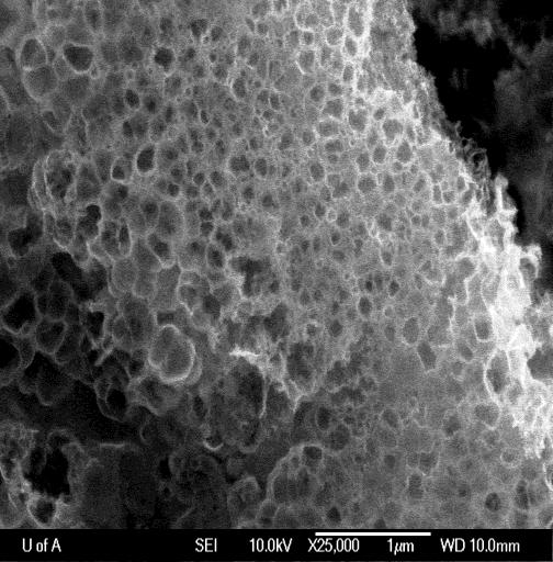
7 LIST OF FIGURES Figure 1-1 Pathways of hydrogen generation 2 Figure 1 2 Band structure of semiconductor 4 Figure 1-3 Schematic diagram of the evolution of a nanotube array at constant anodization voltage 16 Figure 2-1 Illustrative drawing of a two-electrode electrochemical cell in which the Ti samples are anodized 21 Figure 2-2 Photo of the experimental set-up for photocurrent measurement. 25 Figure 2-3 Photo of Kelvin Probe used for SPV measurement. 26 Figure 3-1 Illustrative FESEM images of highly-ordered TiO2 nanotubar array anodized under different conditions. All samples were annealed at 200 for 6 hours. 33 Figure 3-2 TEM images and corresponding TEM diffraction patterns of asfabricated TiO2 nanotubes (without annealing) made at 10 V, 20V and 30V. 37 Figure 3-3 TEM diffraction patterns of TiO2 nanotubular arrays anodized at 10V and 20V and annealed at 200 and 450, respectively. 40 Figure 3-4 Diffuse reflectance adsorption spectra of TiO2 nanotubes fabricated at 10 V and 20V with different heat treatments. 42 Figure 3-5 Photocurrent response of TiO2 nanotubular arrays fabricated at 10V and 20V and annealed at 200 and 450, respectively. 45 Figure 4-1 SEM Top view and cross-sectional images of TiO2 nanotubular arrays prepared by anodizing Ti foil at 50V for I hour at (A) RT and (B) 100 C, respectively. 54 Figure 4-2 TEM images and diffraction patterns of TiO2 nanotubes prepared at RT (A, B) and 100 C (E, F) in the NH4-contained electrolyte, respectively. The near single-crystal diffraction pattern of anatase as the inserted image in A was occasionally observed. C and D are High-resolution TEM of nanotubes fabricated at RT. It s confirmed that the nanotubes fabricated at RT consist of both anatase and rutile phases. The nanotubes fabricated at
8 100 C are mainly in anatase state. Some obscure and weak rings are present in the diffraction pattern of nanotubes fabricated at 100 C, which come from a small amount of residual rutile phase. 56 Figure 4-3 Diffuse reflectance adsorption spectra of TiO2 nanotubes fabricated at RT (cyan) and 100 C (sparse). The inserted is a plot transformed Kubelka- Munk function vs. the energy of light. 60 Figure 4-4 Photocurrent responses of TiO2 nanotubes fabricated at 100 C and RT, respectively. 62 Figure 4-5 SPV spectra of as-anodized TiO2 nanotube arrays fabricated at (A) RT and (B) 100 C. 63
9 Chapter One Introduction
10 1. INTRODUCTION 1.1 Background Development of clean and renewable energy technologies is one of the most strategically important areas in the 21st century, due to the considerably comsuption of fossil fuel, which is considered to be responsible for air quality decline and global climate change. Every year, a larger percentage of the global population seeks to improve their standard of living by burning ever-increasing quantities of carbon-rich fossil fuels. It has been a heavy burden for environment. In addition, fossil fuels are nonrenewable, that is, they draw on finite resources that will eventually dwindle, becoming too expensive or too environmentally damaging to retrieve. The diminished fossil fuel supply, increases the demand for energy and a need to sustain a healthy environment have spurred an extensive search of alternative energy sources, which are renewable and clean. In contrast to fossil fuels, renewable energy resources are constantly replenished and will never run out. Among the alternative energy sources, hydrogen stands first in the rank of possible fuels of the future. Hydrogen, as one of the most abundant elements on the earth, can be found in many organic compounds, and in water. But it doesn t occur naturally as a gas. It is always combined with other elements, including O, F, Cl, etc. Once separated from another element, hydrogen can be burned as a fuel or converted into electricity. The most important facts that make hydrogen fuel attractive are its high energy content and pollution-free nature. Although hydrogen is anticipated to be a potential viable alternative, success of hydrogen fuel largely depends upon its production technology, which should be low cost and environmentally friendly. Separation of hydrogen in natural gas and organic compounds generates large amount of carbon, overshadowing the advantage of hydrogen as a clean fuel. 1
11 1.2 Overview of Hydrogen Generation Hydrogen generation from natural gas reforming Hydrogen can be produced using diverse domestic resources including fossil fuels, such as natural gas and coal, nuclear, hydroelectric, biomass, and renewable sources such as wind, solar, and geothermal[1]. The main method for hydrogen generation is natural gas reforming, which accounts for 95% of hydrogen production today[2]. Steam reforming of methane is a process in which hydrogen can be produced from methane in natural gas using high temperature steam[1]. In a similar liquid reforming process liquid fuels such as ethanol are reacted with steam at high temperature to produce hydrogen near the point of end-use. In gasification, coal or biomass is converted into gaseous components and then synthetic gas, which is reacted with steam to produce hydrogen[1]. This largescale process normally takes place at a temperature of 850 under a pressure of 0.25 MPa (2.5 bar). Figure 1-1 Pathways of hydrogen generation Hydrogen generation from water splitting Since the supply of natural gas is limited, it becomes obvious that water would be the ideal and most sustainable source (e.g., ocean) for hydrogen generation. There have been different processes for hydrogen production through water splitting. 2
12 Electrolysis uses electricity generated by wind, solar, geothermal, nuclear, or hydroelectric power to split water into hydrogen and oxygen[1]. This process has an efficiency of around 70 %. Thermochemical water splitting is achieved at high temperatures generated by solar concentrators or nuclear reactors to drive chemical reactions that split water to produce hydrogen. In photobiological process, microbes such as green algae consume water in the presence of sunlight producing hydrogen as the by-product. Similarly, photocatalytic and photo-electrochemical systems produce hydrogen from water using special semiconductors and energy from sunlight[1]. Theoretically, sunlight can be used to excite a semiconductor, which acts as a catalyst for the water splitting reaction in an electrochemical cell. In practice, the progress in the photo-electrochemical water splitting technology is materialslimited. Metal oxide semiconductors appear to exhibit superior properties as photo-electrodes in comparison to other types of materials because it have the following advantages: (1) its possible to find some semiconductors with a band gap that suitable for capturing energy as much as possible from incident light; (2) many of them are stable in in a wide range of aqueous electrolytes and able to minimize charge carrier recombination; (3) they are in a plentiful supply and environmentally benign for scalable applications. 1.3 Semiconductor photocatalytic hydrogen production Mechanism of semiconductor photocatalytic water splitting A semiconductor consists of conduction band (CB) and valance band (VB). The energy difference between these two levels is called the band gap (Eg). Without excitation, electrons are in valence band. When semiconductors are exposed to photons with energy equal to or higher than their band gap energy level, electrons 3
![receive energy from the photons and are thus excited from VB to CB if the energy gain is higher than the band gap energy leaving holes in the VB[3].](/docs-images/94/120308648/images/13-0.jpg "The photogenerated electrons and holes can recombine in bulk or on surface of the semiconductor within a very short time, releasing energy in the form of heat or photons.")
13 receive energy from the photons and are thus excited from VB to CB if the energy gain is higher than the band gap energy leaving holes in the VB[3]. The photogenerated electrons and holes can recombine in bulk or on surface of the semiconductor within a very short time, releasing energy in the form of heat or photons. Electrons and holes that migrate to the surface of the semiconductor without recombination can, respectively, reduce and oxidize reactants adsorbed by the semiconductor[3]. Figure 1-2 Band structure of semiconductor The reduction and oxidation reactions are the basic mechanisms of photocatalytic hydrogen production. Both surface adsorption and photocatalytic reactions can be enhanced by nano-sized semiconductors as more reactive surface area is available[3]. 4
14 1.3.2 Factors that influence the hydrogen production efficiency of semiconductors Besides the properties of semiconductors, a number of other factors such as the preparation condition, presence of impurities, nature of the reaction media, presence of electron mediators and hole scavengers in solution, etc., also affect the photocatalytic efficiency of the materials[4]. Some of these factors with specific examples are discussed in this section Surface Area Based on the heterogeneous catalysis, it was generally expected that the efficiency of catalytic reaction increases with an increase in surface area. However, formal attempts with colloidal semiconductors to improve the efficiency by increasing the surface area didn t show expected improvement. In addition, when semiconductor powder materials used for hydrogen production, it is shown that there is no direct correlation between surface area of these materials and hydrogen production efficiency [4]. Thus for a certain semiconductor, experiments are needed to find out the optimal surface area needed to get the maximum efficiency. Reber and co-workers investigated the effect of surface area on the hydrogen production efficiency of CdS semiconductor powders [5]. They found that the photocatalytic activity of CdS powders strongly depended on their specific surface area. Only CdS photocatalysts with very low (C6.7 m 2 /g) specific surface areas produced hydrogen with a significant rate. CdS powders precipitated by classical methods have specific surface areas larger than 10 m 2 /g and are consequently almost inactive. High yields of hydrogen could be obtained with CdS samples with very large (>> 100 m /g) or very low (< 6.7 m /g) specific surface areas. In the range between these two domains, yield of hydrogen is close to zero. Photochemical reactions at the semiconductor-electrolyte interface can occur if charge carriers generated by absorbed light reach the interface during their life time and find suitable reaction partners, protons for electrons and donor 5
15 molecules for holes. Moreover, a low surface recombination rate of electrons and holes is an essential condition for carriers reaching interface to react with suitable adsorbed species. In the range of large surface areas, the diffusion length of charge carriers is large compared to size of the particles. For very small particle, no internal electric field is necessary to separate photo-generated electron-hole pairs. Therefore, the possibility for the charge carriers to reach the interface increases as the size of particles decreases. In the range of low specific surface areas, the ratio bulk to interface is significantly larger and consequently, efficiency of charge separation process depends on the presence of a depletion layer. In the range where CdS microcrystals are too thin to build-up such a layer, efficiency of charge separation is expected to increase with increasing size of semiconductor particles until these microcrystals reached the thickness of the space charge layer. An almost identical behaviour has been observed for ZnS powders. However Pt/TiO 2, particles show different properties where the photoactivity increases continuously with increasing specific surface area. Coprecipitation of CdS with about wt % silver sulfide or surface modification of CdS with a large specific surface area by silver ions permitted preparation of very active platinized photocatalysts for the photochemical production of hydrogen from solutions containing S 2- ions as hole scavenger. In solutions containing both S 2- and SO 2- ions, hydrogen is generated concomitantly with thiosulfate ions with a quantum yield of 0.37 with the most active photocatalyst of cadmium zinc sulfide containing Ag 2 S. However, these photocatalysts are less stable than platinized powders of pure CdS of low specific surface area Preparation Methods Semiconductor particles loaded with metals (especially the transition series) show higher efficiency towards hydrogen production compared to pure semiconductor particles. Investigations however have shown that the method of metallization to 6
16 increase either the absorption of the host semiconductor in the visible region or the electron-transfer efficiency (catalytic activity) is an important factor to be considered. Two widely used methods of metallization are photo deposition and thermal deposition. Reber and coworkers [6] used a method of photoplatinization of CdS particles by the photoreduction of Pt (lv) ions or a platinum complex with UV light in the presence of acetic acid. They also explained different treatment methods for photoplatinization. Hydrogen production efficiency of CdS particles is considerably increased by different methods of photoplatinization. Thermal deposition of a series of transition metal ions over WO 3, has been reported [7] by Maruthamuthu and co-workers. Brief procedure for this high temperature sintering technique is described as follows [7]: an aqueous slurry of WO 3 containing known quantities of the metal ions was stirred for homogenous mixing followed by evaporating the solution to dryness in an oven. Dried sample was then grounded to powder, loaded onto a silica boat and sintered at C for 2-3 hours. The hydrogen production efficiency of WO 3 was enhanced by the metal loaded samples prepared using the above method. The mechanism of improving the efficiency of semiconductors by the metals loaded by photo or thermal methods may be due to several mechanisms. These metals (i) can simply act as sensitizers to increase the visible light absorption efficiency of the host semiconductors [7], known as photosensitization, (ii) may involve in the electron-transfer reactions, such as capturing and transferring of conduction band electrons and/or valance band holes [8] and prevent electronhole recombinations, and (iii) can behave as active sites for hydrogen ion reduction reaction [9]. 7
17 Other factors The quantity of metals (photo- or thermal deposited) present in a given amount of the host semiconductor is also one of the most important factors that decide the catalytic efficiency. The quantity of metal catalysts (weight/mole percentage) plays an important role in activating or deactivating the semiconductor photocatalysts for the hydrogen production reaction. For example, Sakata and coworkers [10] reported a remarkable catalytic effect of RuO 2 on powdered TiO 2 for hydrogen evolution from an ethanol-water mixture. It was found that the hydrogen evolution rates from a water-ethanol mixture using various powdered TiO 2 photocatalysts. RuO 2 /TiO 2 powders showed good activity even though RuO 2 had been reported to be an oxygen evolution catalyst. In order to investigate the supporting effect of RuO 2 on TiO 2, the amount of RuO 2 on a fixed amount of TiO 2 was varied. Hydrogen evolution rate for 0.4 x 10m 3 (molar ratio) RuO 2 /TiO 2 was 30 times higher than that for TiO 2 alone and continuously increased as the amount of RuO 2 increased and reached the maximum at the above molar ratio beyond which a decrease was observed as the concentration of RuO 2 was further increased. Stabilizing sulfide semiconductors using polymeric materials [11] for the photostability is also a critical factor in determining the recycling efficiency of these materials Hydrogen generation using TiO 2 Semiconductors, in presence of light energy, are capable of decomposing water into hydrogen and oxygen when their conduction band level is more negative than the hydrogen reduction level and valance band edge is more positive than the water oxidation level for an efficient production of hydrogen and oxygen from water by photolysis[4]. Some semiconductors satisfy the conditions and have been tested as photoanodes in different photoelectrochemical systems, including: TiO 2 [12-15], SrTiO 3 [16-20], Nb 2 O 5 [21-23], SnO 2 [24-27], WO 3 [9, 28, 29], 8
18 CdS[30-32], etc. TiO 2, as a stable, non-corrosive, environmentally friendly, abundant and cost effective semiconductor, is more promising compared to others. Especially highly ordered TiO 2 nanotube arrays, which can offer a large internal surface area and well-oriented crystalline (after annealing) nanotubular arrays, make them to be excellent electron percolation pathways for vectorial charge transfer between interfaces [33, 34]. In addition, the nanotubular array structure can also offer the ability to influence the adsorption and propagation of light through the architecture by precisely designing and controlling the architectural parameters including nanotube pore size, wall thickness as well as the tube length[35]. 1.4 Fabrication of TiO 2 Nanotubular Arrays Through Anodization TiO 2 nanotubular arrays have attracted great attention in both research and industry because of their potential applications in different areas including hydrogen production by water photoelectrolysis [36, 37], gas sensing [38-41], photovoltaic cells [42-44], drug delivery [45-47], and semiconductor devices [48, 49]. A variety of methods have been developed to fabricate such as hydrothermal process [50, 51], template-assisted sol-gel process [52, 53], seeded growth [54], among which, anodization of titanium is the most desirable route to fabricate highly-ordered TiO 2 nanotube arrays with precise control of length, pore size and wall thickness. In 2001, Grimes and co-workers[33] first reported fabrication of TiO 2 nanotube arrays through anodization of titanium foil in a fluoride-containing electrolyte followed by annealing. Since then, considerable research has been carried out to study various influencing factors on properties of as-anodized TiO 2 nanotube arrays including anodization voltage [55], electrolyte composition and ph [56-58], anodization time [56-59], cathode material [59] and annealing temperature [56-58, 60]. 9
19 1.4.1 Anodization in HF-based Electrolyte In 2001, Gong and co-workers reported the anodization of Ti foils at voltages ranging from 3V to 20V in a 0.5wt% HF aqueous electrolyte [33]. When the voltage was as low as 3V, only porous film with pore size of nm could be formed. When the voltage was increased to 10V, tube-like features started to appear on the surface. Inner diameters of the nanotubes increased from 22 nm to 76 nm, as well as the wall thicknesses from 13 nm to 27 nm and lengths from 200nm to 400 nm when increasing the anodization voltage from 10V to 20V. If anodized at a voltage higher than 23V, the tubular structure could not form. In addition, an electrically insulating barrier layer that separated the nantubes from the conducting Ti foil was observed when anodization proceeded for 45 min. Beranek and co-workers also tried H 2 SO 4 to see how the addition of H 2 SO 4 would influence the nanotubular geometry. They investigated the formation of porous TiO 2 on titanium in an electrolyte composed of H 2 SO 4 electrolytes and low concentrations of HF~ wt% [61]. They were able to fabricate highly ordered porous TiO 2 that consisted of pore arrays with single pore diameter of 140 nm and a pore spacing of 150 nm under optimized electrolyte conditions and extended polarization [61]. They also observed that during the formation process, significant current oscillations occurred, depending strongly on the HF content of the electrolyte[61]. Scanning electron microscope and X-ray photoelectron spectroscopy investigations show that the porous layer formed with a competition of TiO 2 formation and oxide dissolution up to a limiting thickness of 500 nm, and that the duration for complete self-ordering in the investigated systems was in the order of several hours. The anodization in acid-containing electrolyte at different temperatures was also studied. Mor and co-workers reported that the addition of acetic acid to 0.5wt% HF electrolyte in a 1:7 ratio resulted in more mechanically robust nanotubes without changing their shape or size[62, 63]. However, the anodization in this acetic acid-containing electrolyte at different temperatures (5, 25, 35 and 50 C) 10
20 led to changes in the wall thickness by approximately a factor of four and the tube-length by approximately a factor of two; the wall thickness increased with decreasing anodization temperature from 9 nm at 50 C to 34 nm at 5 C while the length of the nanotubes increases with decreasing anodization bath temperature from 120 nm at 50 C to 224 nm at 5 C[36]. Ruan and co-workers investigated the anodization of titanium foil in aqueous electrolytes containing 1% HF + 2.5% HNO 3 in the presence and absence of boric acid [64, 65]. During the anodization, the applied anodic potential was initially ramped from 0 to 20V at a rate of 6 V/min and then held constant at 20V for 4 h. In HNO 3 HF electrolyte, the current density rapidly decreased with formation of the barrier layer, which then slightly increased with formation of the porous structure, and then stayed relatively stable with time. The as-fabricated nanotubes showed a uniform, clean, regular structure with an average pore size of about 100nm and a wall thickness about 20nm. The length of nanotubes was found to be around 400 nm. In contrast, with the presence of boric acid (0.5 M), the current densities decreased relatively slowly to a minimum, and then afterwards slowly increased reaching a plateau at approximately 110 min. The TiO 2 nanotube array was found to have a precipitate layer around 400 nm thick, which could be removed by washing with a dilute HF solution. In these samples, there is a greater degree of pore irregularity, with sizes ranging from 10 to 120 nm. The average wall thickness of the nanotubes was 20 nm, and nanotube length was about 560 nm. On summary, the electrolyte composition, including the concentration of HF and addition of other acids, will affect the geometry of the as-fabricated samples. When the concentration of HF is low with presence of H 2 SO 4, only porous structures formed. 11
21 1.4.2 Anodization in electrolytes containing fluoride salts In order to enlarge the anodization potential range for nanotube formation and have better control of the tubular geometry, researchers tried to use electrolyte containing fluoride salts. The formation of TiO 2 nanotubes is strongly affected by the electrolyte. Cai and co-workers studied the effect of electrolyte composition on fabrication of TiO 2 nanotube arrays by anodization [66]. In electrolyte containing 0.1M KF and 1M H 2 SO 4, nanotubes could be formed in the potential range of 10-25V. The diameter of the resulting nanotubes increased from 40nm to 110nm when increase the potential from 10V to 25V. When the potential was too low, the electrochemical etch rate was slow and only a few pits could be seen on the sample surface. On contrary, when the potential was increased to 30V, the electrochemical etch was so fast that the formation of nanotube was provented, and only highly disturbed porous structures were obtained. They also found that electrolyte PH was an important influencing factor on morphology of as-fabricated nanotubes [66]. For example, at 25V, when increasing the ph from strong acidity (ph<1) to weak acidity (ph 4.5), the nanotube length was increased from 0.56 μm to 4.4 μm; at 10V, the length increased from 0.28μm (ph<1) to 1.4 μm (ph 5). It was also shown that for a particular ph, the length increases with applied potential. When the potential increased from 10V to 25V, the length increased from 0.59 μm to 1.5 μm for ph=2.8 and from 1.05 μm to 4.4 μm for ph=4.5. The optimal ph range for formation of relatively longer nanotubes is between ph 3 and ph 5; lower ph forms shorter but clean nanotubes, while higher ph electrolytes result in longer tubes that suffer from unwanted precipitates [66] Anodization in organic electrolytes It is believed that the donation of oxygen in organic electrolytes is more difficult to occur, compared to that in aqueous electrolytes. The reduction in water content reduces the chemical dissolution of the oxide in the fluorine containing 12
22 electrolytes, and then aids longer-nanotube formation [38, 64]. Many different electrolytes, including formamide (FA), N-methyl formamide (NMF), ethylene glycol, dimethyl sulfoxide (DMSO) and glycerol, have been studied. It is found that the key factor for achieving very long nanotube arrays is to minimize water content in the anodization bath to less than 5%. Paulose and co-workers first investigated the anodization of Ti foil in formamidecontaining electrolytes [67]. TiO 2 nanotubular arrays nearly 70 μm long were fabricated by anodization in formamide electrolytes containing 1-5 wt % of deionized water and wt % NH 4 F for 48 hours at a constant potential of 35 V. The average outer diameter of these nanotubes was 180 nm, and wall thickness was around 24 nm. It was also found that higher anodization potentials resulted in longer nanotubes with larger diameters. Because with an increase in the potential, there would be increased driving force for ionic transport through the barrier layer at the bottom of the pore, which results in faster movement of the Ti/TiO 2 interface into the Ti metal. In the FA/NMF electrolytes, an increase in the outer nanotube diameter was found to increase with anodization voltage[67]. Ruan and co-workers investigated anodization of titanium in a fluorinated dimethyl sulfoxide (DMSO) and ethanol mixture electrolyte [68]. The prepared anodic film had a highly ordered nanotubular array surface architecture. At 20V, nanotubular arrays with an inner diameter of 60 nm and wall thickness of 40 nm were formed. The overall length of the nanotube arrays was controlled by the duration of the anodization. Nanotubes started to appear after approximately 48 h and anodization for 72 h resulted in a nanotubular array approximately 2.3 µm in length. The photoelectrochemical response of the nanotube-array photoelectrodes was studied using a 1 M KOH solution under both UV and visible (AM 1.5) illumination. Enhanced photocurrent density was observed for samples obtained in the organic electrolyte, with an UV photoconversion efficiency of 10.7% [68]. They also found that in comparison with electrochemical etching of titanium in fluorinated aqueous solution the etching of titanium in fluorinated organic 13
23 electrolyte was a relatively slow process [68]. Later, Yoriya and co-workers fabricated TiO 2 nanotubes by anodization in an electrolyte of dimethyl sulfoxide (DMSO) containing 2% HF electrolyte at 40V for 69 hours. The as-anodized nanotubes had a length of approximately 45 µm, with pore diameter around 120 nm and wall thickness around 15 nm [69]. With increasing the anodization potential from 20V to 60V for 70 hours, the length of high-ordered nanotubes increased from around 10µm to 93µm. At 20V, when the HF concentration was increased from 1% to 4%, the length of the nanotubes increased from 4.4 μm to 29 μm. A two-step anodization process was applied, and it was found that Preanodization at 20V in 0.5% HF in deionized water followed by anodization at 40 V in DMSO containing 2% HF solution yielded 82 μm long nanotubes, which was almost two times as long as those obtained without using the pre-anodization step[69]. TiO 2 nanotubular arrays were also fabricated by anodization of Ti foil in the voltage range 20-65V in ethylene glycol (EG) electrolytes containing wt% NH 4 F and 1% - 4% H 2 O [38, 64, 70]. It was reported that for a given concentration of water, the length increased with increasing NH 4 F up to 0.3 wt %. When NH 4 F concentration was raised up to 0.3 wt %, the nanotube length increased with increasing H 2 O concentration up to 2 vol%. Prakasam and co-workers developed a double-sided anodization process [70] in an electrolyte composed of water NH 4 F and ethylene glycol, two highly ordered, hexagonal closed-packed titania nanotube arrays 360 µm in length that are separated by a thin compact oxide layer were obtained[70] Anodization in organic-inorganic mixed electrolyte Efforts were also made to discover how electrolyte composition influence the nanotube geometry. Lai and co-workers studied the formation of self-organized TiO 2 nanotube array films by electrochemical anodization in a deceloped organic- 14
24 inorganic mixed electrolyte [71]. They were able to control the pore-size and wall thickness of as-anodized TiO 2 nanotubes by optimizing electrolyte composition and anodization condition. For example, the TiO 2 nanotube array could be obtained in a voltage range of 5 to 33 V in the glycerol and DI water mixed solution containing 0.5 wt% NaF and 0.2M Na 2 SO 4. The diameters of the tubular TiO 2 increased with the anodizing voltage, from about 20nm at 5V to 150 nm at 33V [71]. The thickness first increased rapidly from about 0.23µm at 5V to 2.6µm at 10V. It was followed by a slow increase to reach approximately 3.1µm at 20V. Anodizing at 25 V, the growth rate of the nanotubes reached a maximum value (approximately 4.7µm). However, if the applied potential was further increased, the thickness of the oxide layer decreased[71]. Although there has been great progress towards controlling the morphology of the anodically fabricated TiO 2 nanotube arrays, the development on how to improve the crystallinity of the as-anodized is really limited. The as-fabricated nanotubes are always amorphous. 1.5 Mechanism of TiO 2 nanotube anodizaton Besides the fabrication of TiO 2 nanotubes, anodization has been widely used to produce nanoporous Al [72, 73] and Si [74-76], ZrO 2 nanotubes [77-79], HfO 2 nanotubes [80, 81]. The mechanism responsible for the formation of TiO 2 nanotubes is believed to include the following key processes [82-84]: 1) Oxide growth at the surface of the metal substrate as a result of the interaction of the metal with O 2 - or OH- ions [85]. 2) Migration of anions through the oxide layer reaching the metal/oxide interface where they react with the metal. 3) Migration of metal ions (Ti 4+ ) from the metal at the metal/oxide interface. Ti 4+ cations are ejected from the metal/oxide interface under application of an electric field that moves towards the oxide/electrolyte interface. 15

25 4) Field assisted dissolution of the oxide at the oxide/electrolyte interface. Due to the applied electric field the Ti-O bond undergoes polarization and is weakened, promoting the dissolution of the metal cations. Ti 4+ cations dissolve into the electrolyte, and the free O 2- anions migrate towards the metal/oxide interface to interact with the metal [86]. 5) Chemical dissolution of the metal or oxide by the acidic electrolyte takes place during anodization. Chemical dissolution of titania in the HF electrolyte plays a key role in the formation of a nanotubular versus nanoporous structure. No nanotubes can be formed if the chemical dissolution is too high or too low[38, 64]. Figure 1-3 Schematic diagram of the evolution of a nanotube array at constant anodization voltage With the onset of anodization, a thin layer of oxide forms on the titanium surface, due to the interaction of the surface Ti 4+ ions with oxygen ions (O 2- ) in the electrolyte. The reaction are presented by the following equations: 2H 2 O O 2 + 4H + + 4e - [1-1] Ti + O 2 TiO 2 [1-2] 16
26 In the initial stages of the anodization process field-assisted dissolution dominates chemical dissolution due to the relatively large electric field across the thin oxide layer[86]. Then, small pits originate in this oxide layer because of the localized dissolution of the oxide, which makes the barrier layer at the bottom of the pits relatively thinner and increases the electric field intensity across the remaining barrier layer, resulting in further pore growth[38, 64], as presented by: TiO 2 + 6F - + 4H + TiF H 2 O [1-3] The pore entrance is not affected by electric field-assisted dissolution and hence remains relatively narrow, while the electric field distribution in the curved bottom surface of a pore causes pore widening, as well as deepens of the pore. These make the pore have a scallop shape [87]. Since the Ti-O bond energy is high (323 kj/mol) [87], in the case of TiO 2, it is reasonable to assume that only pores that have thin walls can be formed due to the relatively low ion mobility and relatively high chemical solubility of the oxide in the electrolyte, so un-anodized metallic portions can exist between the pores. With the pores grow deeper, the electric field in these protruding metallic regions increases, which enhences the field-assisted oxide growth and oxide dissolution. Hence simultaneously with the pores, well-defined inter-pore voids start forming. Thereafter, both voids and tubes grow in equilibrium. The nanotube length increases until the electrochemical etch rate equals the chemical dissolution rate of the top surface of the nanotubes [64]. After that, the nanotube length will be independent of anodization duration. The rate of electrochemical etching (field-assisted oxidation and dissolution) depends on the anodization potential as well as the composition of electrolytes. If the electrochemical etching proceeds faster than the chemical dissolution, the thickness of the barrier layer increases, which in turn reduces the electrochemical etching process to the rate determined by chemical dissolution. The chemical 17
27 dissolution rate is determined by the F- concentration and solution ph. With increasing F - and H + concentrations, chemical dissolution increases. Recent investigations have shown that only in a certain F - concentration range nanotube arrays can be achieved [38, 64]. The anodic potential at which nanotubes are formed is related to the F - concentration, with higher potentials that requires electrolytes of higher F - concentrations. In organic electrolytes such as formamide (FA), N-methylformamide (NMF), dimethyl sulfoxide (DMSO) and ethylene glycol (EG), water is usually the main source of oxygen in anodizing solutions. It is believed that hydroxyl ion can be injected from the electrolyte into the anodic oxide film during anodization [88]. When a large amount of water is present, hydroxyl ions are injected into the body of the oxide layer and affect the structure sufficiently to impede ion transport through the barrier layer [89], which is necessary for further movement of the metal-oxide interface into the metal. However, when less water is present, the difficulty in extracting oxygen and/or hydroxyl ions from the solution limits the rate of growth of the overall oxide film. In addition, the barrier oxide layer exhibits increased ionic conductivity caused by the non-stoichiometry induced by the reduced hydroxyl ion availability to the oxide. The amount of hydroxyl ion injection is dependent on the solvent structure[67, 70, 90, 91]. 1.6 Crystallization of TiO 2 Nanostructures Crystalline structures are required for photocatalytic activity because they can provide a direct and fast pathway for electron transport and then decrease the electron lifetimes in the semiconductor electrode [92]. Shorter lifetimes can reduce the electron recombination reactions with the oxidized species in the electrolyte, which in turn increase the overall conversion efficiencies. Several processing routes have been used to fabricate crystalline TiO 2 including hydrothermal, sol-gel and calcination processes. However, crystallization by 18
28 hydrothermal treatment is not convenient since it leads to a strong reduction of the textural properties due to excessive coalescence of the inorganic framework, resulting in structural damage when hydrothermal treatment is performed on mesostructured titania [93]. With the sol gel process, titania nanoparticles usually exhibit a high tendency to aggregate. Similarly, with calcination the thusgenerated TiO 2 crystals are usually too large to be accommodated within mesopore walls, which leads to structural collapse[93]. Therefore, many researchers have been working on developing low temperature synthesis routes, where with the attempt to get rid of a high temperature annealing step for crystallization, during which the growth of a barrier between the nanotubes and the substrate and cracking negatively affect the nanotubes. 1.7 Research Objective The main objective of this work is to develop in-situ one-step fabrication process for crystalline highly ordered TiO 2 nanotube arrays through anodization, without subsequent high temperature annealing for crystallization. Efforts were also made to investigate the geometries and corresponding properties of TiO 2 nanotubular arrays anodized at elevated temperatures. Two different electrolyte systems and various anodization temperatures were explored. Relevant issues were also investigated. 19
29 Chapter Two Experimental Methods and Materials
30 2. EXPERIMENTAL METHODS AND MATERIALS 2.1 Potentiostatic Anodization Highly ordered TiO 2 nanotube arrays were fabricated through potentiostatic anodization in a conventional two-electrode electrochemical cell at different temperatures. A 0.2-mm-thick titanium foil with a size of 20mm x 20mm (Alfa Aesar, 99%) was used as a working electrode, and a platinum foil with the size of 10mm x 10mm served as the counter electrode. The distance between the working electrode and the counter electrode was about 2cm. The anodization was carried out under different potentials using a DC power supply (1715A, B&K Precision Corp.). A Fisher Scientific Hi-temp Bath (Model 160A) was used for heating with wax as media. Titanium foils were soaked into the mixture of HF, HNO 3 and H 2 O with volume ratio of 1: 3: 10 for 20s to remove the oxide layer on the surface. Mainly two different electrolytes were used. One is containing 0.2 wt % mixed ammonium fluoride (ACS reagent, Fisher Scientific) and ammonium chloride (ACS reagent, Fisher Scientific) and 2 vol % water. The mole radio of fluoride to chloride is 1:1; the other is composed of 0.05 wt% NH 4 F, 2vol% H 2 O and glycerol (99.5%, Fisher Scientific). Some as-prepared samples were finally annealed at in a tube furnace (Thermocraft, Inc.) with a heating/cooling rate of 0.5 C min

31 Figure 2-1 Illustrative drawing of a two-electrode electrochemical cell in which the Ti samples are anodized 2.2 Morphology and Crystal Structure Characterization Scanning Electron Microscopy A scanning electron microscope, attached with an energy-dispersive X-ray spectroscope, was used to examine the morphology and dimensions of fabricated TiO 2 nanotubular arrays. As defined in wikipedia, A scanning electron microscope (SEM) is a type of electron microscope that images a sample by scanning it with a high-energy beam of electrons in a raster scan pattern. The electrons interact with the atoms that make up the sample producing signals that contain information about the sample's surface topography, composition, and other properties such as electrical conductivity. The types of signals produced by an SEM include secondary electrons, back-scattered electrons (BSE), characteristic X-rays, light (cathodoluminescence), specimen current and transmitted electrons. Secondary electron detectors are common in all SEMs, but it is rare that a single machine would have detectors for all possible signals. The signals result from interactions of the electron beam with atoms at or near the surface of the sample. A field-emission cathode in the electron gun of a scanning 21
32 electron microscope provides narrower probing beams at low as well as high electron energy, resulting in both improved spatial resolution and minimized sample charging and damage. It can produce clearer, less eletrostatically distorted images with spatial resolution down to 1.5 nm, which is 3 to 6 times better than conventional SEM. So it is widely used to analyze film thickness and construction details for nanomaterials. A Field Emission Scanning electron Microscope (JEOL JSM6301FXV) was used to analyze the morphology of the samples including pore size, wall thickness and tube length. The images were taken in an accelerating operating voltage of 5 or 10kV Transmission Electron Microscopy Transmission Electron Microscopy (TEM) is a microscopy technique whereby a beam of electrons is transmitted through an ultra thin specimen, interacting with the specimen as it passes through it. An image is formed from the electrons transmitted through the specimen, magnified and focused by an objective lens and appears on an imaging screen. TEM examinations were carried out for TiO 2 samples by scratching a portion of the TiO 2 nanotubes from the respective discs into alcohol, followed by ultrasonication for 3-5 minutes so that they can disperse better in alcohol. Selected area diffraction (SAD) is a crystallographic experimental technique that can be performed inside a TEM. When a thin crystalline specimen is subjected to a parallel beam of high-energy electrons, the electrons pass through the sample easily. In this case, electrons are treated as wave-like, rather than particle-like (see wave-particle duality). Because the wavelength of high-energy electrons is a fraction of a nanometer, and the spacing between atoms in a solid is only slightly larger, the atoms act as a diffraction grating to the electrons, which are diffracted. That is, some fraction of them will be scattered to particular angles, determined by 22
33 the crystal structure of the sample, while others continue to pass through the sample without deflection. As a result, the image on the screen of the TEM will be a series of spots the selected area diffraction pattern (SADP), each spot corresponding to a satisfied diffraction condition of the sample's crystal structure. If the sample is tilted, the same crystal will stay under illumination, but different diffraction conditions will be activated, and different diffraction spots will appear or disappear. Electron diffraction analysis and imaging were carried out with a JEOL 2010 transmission electron microscope equipped with a Noran UTW X-ray detector. SED was applied to determine the crystalline state for all the samples Diffuse reflectance UV-Vis techniques When a molecule absorbs ultraviolet or visible light, its electrons get promoted from ground state to higher energy state. Different molecules absorb radiation of different wavelengths. An absorption spectrum will show a number of absorption bands corresponding to structural groups within the molecule. The absorption of UV or visible radiation corresponds to the energy of excitation of outer electrons. Diffuse reflectance relies upon the focused projection of the spectrometer beam into the sample where it is reflected, scattered and transmitted through the sample material (shown on the right). The back reflected, diffusely scattered light (some of which is absorbed by the sample) is then collected by the accessory and directed to the detector optics. Only the part of the beam that is scattered within a sample and returned to the surface is considered to be diffuse reflection. A scanning UV-Vis spectrometer (U-3010, HITACHI) equipped with an integrating sphere, 60mm Dia, was used to determine the reflectance spectra of TiO 2 nanotube arrays over a range of nm at a scan speed of 300 nm min -1, with a reflectance reference of BaSO 4. 23
34 The Kubelka-Munk theory is generally used for the analysis of diffuse reflectance spectra obtained from weakly absorbing samples. It provides a correlation between reflectance and concentration. The concentration of an absorbing species can be determined using the Kubelka Munk formula: F(R) = (1- R) 2 / 2R = k/ s Where: R is the absolute reflectance of the sampled layer, k is the molar absorption coefficient and s is the scattering coefficient. When data are plotted as transformed Kubelka-Munk function versus the energy of light, the intersection of tangent line and x-axis gives the band gap of a semiconductor Photocurrent Measurement In order to investigate the photoelectric property of the TiO 2 nanotube arrays, the photocurrent response experiments were carried out under the visible light pulsedirradiation using an electrochemical workstation (CHI600C, CH Instruments Co.). A standard three-electrode cell with a platinum foil as counter electrode and a saturated calomel electrode (SCE) as reference electrode was used for the photoelectrochemical measurements. The electrolyte was 0.5 M Na 2 SO 4 aqueous solution, and the measuring potential was set to be 0.1 V (vs. SCE). The light source was away from the working electrode with a distance of 10 cm, all experiments were carried out at room temperature. 24

35 Figure 2-2 Photo of the experimental set-up for photocurrent measurement Surface photovoltage measurements Generally, the photovoltaic effect consists of an illumination-induced change in the potential distribution in a given structure, which is typically the result of some charge transfer and/or redistribution within the device due to the incident illumination[94]. A specific variant of the photovoltaic effect is the surface photovoltaic effect. The surface photovoltage (SPV) is defined as the illumination-induced change in the surface potential[94]. This effect, observed at Si and Ge surfaces, was first reported in a short note by Brattain in 1947[95]. 25
 equipped with a Surface Photovoltage")
36 Figure 2-3 Photo of Kelvin Probe used for SPV measurement. In this study, SPV was measured with a Kelvin Probe (SKP 5050) equipped with a Surface Photovoltage Spectroscopy (Add-On Module of SPS040, KP Technology, UK). 26
37 Chapter Three Tailoring the Geometry and Properties of TiO 2 Nanotubes by Raising the Anodization Temperature and Varying the Anodization Voltage
38 3. TAILORING THE GEOMETRY AND PROPERTIES OF TIO 2 NANOTUBES BY RAISING THE ANODIZATION TEMPERATURE AND VARYING THE ANODIZATION VOLTAGE 3.1 Abstract The geometry of TiO 2 nanotubes strongly affects their photocatalytic activity. Since temperature influences the kinetics and dynamics of anodization, it consequently affects the geometry of the nanotubes. However, studies of the TiO 2 nanotube growth at elevated temperatures are rather limited. In this work, the growth of TiO 2 nanotubular arrays at elevated temperatures, mainly 100, under several different anodization voltages were studied. Changes in geometry, band gap and corresponding photocurrent of the nanotubes with respect to the anodization voltage at the elevated temperature were investigated. It was demonstrated that the elevated anodization temperature in combination with the varied anodization voltage strongly influenced the growth of TiO 2 nanotubes and consequently alternated their properties. Efforts are made to understand mechanisms involved and clarify relevant issues. 3.2 Introduction In 2001, Grimes and co-workers[33] reported fabrication of TiO 2 nanotube arrays by anodization of titanium foil in fluoride-containing electrolyte followed by annealing. Since then, a lot of research has been done to study the various factors that influence properties of as-anodized TiO 2 nanotube arrays, including the anodization voltage [55], electrolyte composition and ph value [56-58], anodization duration [56-59], cathode material [59] and annealing temperature [56-58, 60]. Many studies show that the electrolyte composition and its ph value play important roles in the formation of TiO 2 nanotubes. However, most anodization processes were carried out at room temperature. Since temperature influences the kinetics and dynamics of anodization, it is expected that the anodization temperature may affect the geometry of TiO 2 nanotube and thus influences their properties. However, studies on high-temperature anodization of 27
39 TiO 2 nanotubular arrays are very few. Ge and co-workers[60] fabricated TiO 2 nanotube arrays at 35 in a solution consisting of 0.5% HF and acetic acid which were mixed at a ratio of 1: 7. They observed that the length of nanotubes decrease with the increase of bath temperature, and at 45 C only protuberant structure was formed and no tubular structure appeared. Wang and Lin [96] noticed that in aqueous electrolyte the electrolyte temperature in a limited range showed little effect on the TiO 2 nanotube dimensions but this was not the case when anodization was carried out in nonaqueous electrolytes. The studies demonstrate the influence of electrolyte temperature on TiO 2 nanotubular geometry under certain conditions. However, so far studies of the effect of elevated temperatures on TiO 2 nanotube growth are only limited to a small range of elevated temperatures (a few tens of degrees ), and the temperature effect on TiO 2 nanotube growth and corresponding structure and properties have not been well understood and relevant studies are rather limited. Understanding the temperature effect on the geometry of TiO 2 nanotubes is of significance to the fabrication of high-performance TiO 2 nanotubes, since the photocatalytic behavior of TiO 2 nanotubes is largely affected by the nanotubular geometry, e.g., the ratio of the tube length to tube diameter, which influences the electron-hole separation, charge transport and pair recombination[97]. The nanotubular architecture also influences the adsorption and propagation of light [98]. Therefore, it is of importance to control the nanotubular geometry and investigate corresponding photocatalytic properties. Another issue is the possible influence of high temperature anodization on the crystallinity of TiO 2 nanotubes. It is commonly accepted that only crystalline TiO 2 nanotubes are photocatalyically active. However, it is known that amorphous metal oxides have various defects which could modify local energy band structure and could act as possible centers for electron- hole recombination centers. In 2007, Zhang and co-workers reported the photocatalytic property of hydrated amorphous TiO 2 (a-tio 2 [99]. As demonstrated in this chapter, validity 28
40 of the commonly accepted conclusion seems worth being further studied. The objective of studies reported in this chapter is to investigate the geometries and corresponding properties of TiO 2 nanotubular arrays, anodized at elevated temperatures, mainly 100 C, under different voltages in a glycerol electrolyte. Issues related to the crystallinity and photocatalytical activity have also been discussed. The obtained knowledge could help to control the anodization process for optimization of TiO 2 nanotubular arrays structure and properties. 3.3 Experimental Section Fabrication Highly ordered TiO 2 nanotubular arrays were fabricated by potentiostatic anodization, followed by rinsing with deionized water and air-drying. Prior to anodization, titanium foils with a thickness of 0.25 mm (99.5%, Sigma-Aldrich) were soaked into the mixture of HF, HNO 3 and H 2 O with volume ratio of 1: 3: 10 for 20s to remove the oxide layer on the surface. The foils were then experienced potentiostatic anodization at 10 V in a two-electrode electrochemical cell with a platinum foil (12 mm x 12 mm) as the counter electrode in glycerol (99.5%, Fisher Scientific) electrolyte containing 0.2 wt % mixed with ammonium fluoride (ACS reagent, Fisher Scientific), ammonium chloride (ACS reagent, Fisher Scientific) and 2 vol % water. The mole ratio of fluoride to chloride was 1:1. The spacing between the anode and cathode was approximately 5 cm. The reaction was driven by a dc power source. All experiments were done at 100. Some asprepared samples were finally annealed at 200 C for 6 h or 450 for 2h in a tube furnace (Thermocraft, Inc.) with a heating/cooling rate of 0.5 C min -1. Characterization FE-SEM observations were carried out under a JEOL JSM6301FXV scanning electron microscope with a field emission electron source running at 5 and 10 kv and a Hitachi FE-SEM S-4800 at 20 kv. Electron diffraction analysis and imaging 29
41 were made using a JEOL 2010 transmission electron microscope equipped with a Noran UTW X-ray detector. Measurement of the response of fabricated TiO 2 nanotubes to UV light Photocurrents under UV-Vis light irradiation were measured using a commercial electrochemical system (Model PC4-750, Gamry Instruments Inc., Warminster, PA, USA). A scanning UV-Vis spectrometer (U-3010, Hitachi) was used to determine the reflectance spectra of TiO 2 nanotube arrays over a wavelength range of nm at a scan speed of 300 nm/min, with a reflectance reference of BaSO Results and Discussion Geometry and structure Figure 3-1(a-b) show scanning electron micrographic (SEM) images of the morphology of titania nanotube arrays fabricated at 10 V at 100 after annealing. The tubes are open at the top and closed at the bottom. The inner diameters of the nanotubes are mostly around 20 nm, and the lengths range from 400 to 500nm, corresponding to an aspect ratio in the range of 20 ~ 25. The lengths and diameters of the tubes are nearly the same with those fabricated at room temperature by one-hour anodization. However, when the anodization duration was increased, nanotubes anodized at room temperature could grow up to hundreds of microns [91, 100] while the nanotubes made at 100 did not show noticeable increase in length when anodization was prolonged from 1 h to 8 h. The slightly corrugated structure of nanotube walls can be seen in cross-section image (Figure 3-1(d)). This should be addressed to the presence of 2.0 vol% water in NH 4 F contained glycerol electrolyte, resulting in the concentration fluctuations and ph bursts during anodization [101]. 30
")
 100")

")

42 (a) V (b) V (c) V (d) V (e) V (f) V 31
 200 5V")


43 (g) V (h) 200 5V (i) V in glycerol electrolyte contain NH 4 F only 32

44 (j) V in glycerol electrolyte contain NH 4 Cl only Figure 3-1 Illustrative FESEM images of highly-ordered TiO 2 nanotubar array anodized under different conditions. All samples were annealed at 200 for 6 hours. The formation of nanotubular arrays in fluoride containing electrolytes is the result of three simultaneously occurring processes: 1) the field assisted oxidation of Ti metal to form titanium dioxide; 2) the field assisted dissolution of Ti metal ions in the electrolyte; and 3) the chemical dissolution of TiO 2 due to the effect of etching by fluoride ions [33, 55]. Higher anodization temperatures may increase the reaction rate of these processes, which could affect longitudinal growth of the nanotubes. As mentioned earlier, the length of nanotubes did not continuously grow for a prolonged anodization at 100. This implies that higher anodization temperatures could lead to quick establishment of a dynamic balance between oxidation and dissolution, which limits the continuous growth of nanotubes. When the anodization bath temperature was increased to 120, the tube length decreased to nm (Fig. 3-1 (g)). When the bath temperature was further raised to 200, only porous structure formed such as that illustrated in Fig
45 (h). Increasing the anodization voltage enhanced both the field-assisted oxidation of Ti metal and the field-assisted dissolution of Ti metal ions in the electrolyte, leading to accelerated tube growth and increased tube diameter. Within 1 hour, nanotubes anodized at 20V can grow up to 1.5μm (Fig.3-1(d)), while at 10V, they can only grow up to 500nm (Fig.3-1(b)). However, when the anodization voltage was increased to 30V, only sponge-like nanoporous structure formed, which was confirmed by the TEM examination (Fig.3-1 (e) and (f)). Figure 3-2 shows transmission electron microscopic (TEM) images of anotubes fabricated under 10V (a-c), 20V (d-f), and 30V (g-i) at 100. These TEM images confirm the tubular structure and show the influence of the anodization voltage on the nanotube diameter. As determined, the inner diameter of nanotubes increased from less than 20 nm to about 50 nm as the voltage was increased from 10V to 20V. The wall thickness was also increased from 7nm to approximately 10 nm. This is constant with TiO 2 nanotubular arrays fabricated in glycerol+water+ NH 4 F electrolytes [102], but in contradictory to TiO 2 nanotubular arrays anodized in either fluoride-free electrolytes composed of NaCl and KBr[103] or NH 4 F + glycerol electrolyte [55]. We believe that in the present electrolyte system, with the presence of water, NH 4 F play the major part in the anodization process. To confirm this, anodization were conducted in glycerol electrolyte containing NH 4 F only and NH 4 Cl only, respectively. As shown, in electrolyte contain NH 4 F only, nanotubes grew up to more than 1μm (Figure 3-1(i)). However, in electrolyte contain NH 4 Cl only, no nanotubes formed (Figure 3-1(j)). Clearly, the effect of temperature on the geometry of TiO 2 nanotubular arrays is electrolyte dependent. Thus, the architecture or geometry of TiO 2 nanotubular arrays can be largely modified by alternating the combination of bath temperature, voltage, and electrolyte. 34
 10V")
 10V 35")
46 (a) 10V without annealing (b) 10V without annealing (c) 10V without annealing 35
 20V")
 20V 36")
47 (d) 20V without annealing (e) 20V without annealing (f) 20V without annealing 36
 made at 10 V, 20V and 30V.")

48 (g) 30V without annealing (h) 30V without annealing (i) 30V without annealing Figure 3-2 TEM images and corresponding TEM diffraction patterns of asfabricated TiO 2 nanotubes (without annealing) made at 10 V, 20V and 30V. The TiO 2 nanotubular arrays anodized under 10 V and 20 V appeared to be amorphous according to their electron diffraction patterns (Figure 3-2) but they could be in a partial nanocrystalline state with very low crystallinity and extremely tiny crystallites or crystal defects in an amorphous matrix, which may not be reflected by the diffraction pattern. This possibility exists based on the 37
49 following considerations: 1) The as-fabricated nanotubular arrays showed nonezero photocurrent responses as demonstrated later; 2) When the crystallinity is very low with tiny crystalline domains, the electron diffraction may not give a polycrystalline diffraction pattern. Raising the anodization voltage to 30 V led to an increase in the degree of crystallinity and possibly larger crystalline domains, demonstrated by the electron diffraction pattern illustrated in Figure 3-2 (30 V without annealing), in which polycrystalline diffraction rings become visible (Fig.3-2 (g)). It is known that TiO 2 nanotubes made by anodization at the room temperature are generally in an amorphous state and subsequent annealing is needed for crystallization. Increasing the bath temperature may provide a greater thermal force to drive the nanotubes away from the metastable amorphous state. A higher anodization voltage may provide more energy to achieve this. Because of high photocatalytic activity d2 of the nanotubular structure, this work is mainly focused on the TiO 2 nanotubular arrays formed under 10V and 20V, and the porous TiO 2 film made under 30V is no longer analyzed. Heat treatment at 200 and 450 were respectively applied to the nanotubes made under 10V and 20V. TEM diffraction patterns were shown in Fig. 3-3 As shown, annealing at 200 C did not lead to noticeable changes in the crystallinity of the nanotubes due to lower thermal energy but crystallization was obvious when annealed at 450. It is understandable because the crystallization temperature of TiO 2 nanotubes is about 280 C, above which the thermal energy is high enough to drive or rearrange ions at random locations (amorphous) to form a crystalline lattice TiO 2 [ ] with the minimum free energy. 38
 10V 450 annealing")
50 (a) 10V 200 annealing (b) 10V 450 annealing 39

51 (c) 20V 200 annealing (d) 20V 450 annealing Figure 3-3 TEM diffraction patterns of TiO 2 nanotubular arrays anodized at 10V and 20V and annealed at 200 and 450, respectively Properties Properties of both annealed and unannealed TiO 2 nanotubular arrays fabricated 40
52 under 10 V and 20V, respectively, were evaluated. In order to determine their band gaps, diffuse reflectance adsorption spectra were collected, followed by transformation using Kubelka-Munk function. These transformed functions versus the energy of light are plotted in Figure 3-4. The intersection of tangent line and x-axis gives the band gap of a semiconductor. Determined band gaps of the samples are listed in Table 3-1. As shown, the TNAs fabricated under 10V have a band gap of 3.55 ev, which is higher than that of crystalline TiO 2 [109]. The band gap decreased to 3.40 ev when the anodization voltage was increased to 20 V. 41
53 Figure 3-4 Diffuse reflectance adsorption spectra of TiO 2 nanotubes fabricated at 10 V and 20V with different heat treatments. Compared to that of nanotubes fabricated under 10 V, the lowered band gap of 42
54 TiO 2 nanotubes fabricated under 20 V without annealing could be attributed to their increased crystallinity or larger crystalline domains. This is consistent with further increased crystallinity of TiO 2 fabricated under 30 V as demonstrated by their polycrystalline diffraction pattern (Fig.3-2). The crystallinity or the crystalline domain size of the as-fabricated nanotubes was increased by annealing (see polycrystalline diffraction pattern shown in Fig.3-3 (b) and (d)). Annealing provided thermal energy to drive them deviate from a partial crystalline state with very low crystallinity, leading to an decrease in the band gap of, e.g., nanotubes made under 10 V, from 3.55 ev to 3.30 ev by annealing at 200, and further down to 3.13 ev by annealing at 450, as shown in Table 3-1. Similarly, annealing also increased the crystallinity and crystallite size of nanotubes fabricated under 20 V (see polycrystalline diffraction pattern shown in Fig.3-3(d)), resulting in decrease in the band gap from 3.40 ev, through 3.37 ev, to 3.00 ev (Table 3-1). Table 3-1 Band gap and photocurrent response of TiO 2 nanotubular arrays fabricated at 100 under 10 V and 20 V, respectively, with and without annealing ==================================================================== Band gap(ev) photocurrent response(µ A) 10V without annealing V with annealing at V with annealing at V without annealing V with annealing at V with annealing at ========================================================== 43
55 In order to better understand the observed phenomena and evaluate the photocatalytic activities of the nanotubular arrays, photocurrent responses of the samples were measured under UV-Vis light pulsed irradiation, which helped to evaluate their photo-induced charges separation efficiencies. The working electrode potentials were set at 0.1V. The surface area that exposed to light illumination was 1cm 2. Measured photocurrent responses of different samples with different band gaps are also presented in Table 3-1. As shown, the TiO 2 nanotubular arrays with smaller band gaps show larger photocurrent responses or higher photocatalytic activities [110]. Such correlation is understandable, since with lower band gap energy, more light photons from UV-Vis light source are absorbed and utilized, resulting in a higher photocurrent. 44
56 Figure 3-5 Photocurrent response of TiO 2 nanotubular arrays fabricated at 10V and 20V and annealed at 200 and 450, respectively. The consistency between the band gaps and corresponding photocurrent responses 45
57 helps to understand the alternated behavior of the sample anodized and annealed under various conditions. Prior to annealing, the nanotubes fabricated under 10V showed the highest band gap energy of 3.55V and very low photocurrent response. This indicates that this as-anodized sample could not be in an amorphous state though the diffraction pattern showed that it was, otherwise a non-zero photocurrent should not be detected. The nanotubes anodized under 20V showed similar characteristics. When the TNAs anodized under 10 V were annealed at 200, crystallinity could increase, leading to an increased photocurrent response, although the electron diffraction pattern still does not show increased crystallinity (Fig.3-3(a)). When the annealing temperature was raised to 450, the nanotubes showed a further decrease in band gap to 3.13 ev (Table 3-1) accompanied with higher photocurrent response (Fig.3-5) and a distinctive polycrystalline diffraction pattern (Fig.3-3(b)). The situation of the nanotubes made at 20V is similar. It is worth noting that possible crystallization of the nanotubes appears to be strongly affected by the tube size when the annealing temperature is below the crystallization temperature (~ 280 ). As observed, nanotubes anodized under 10V with smaller tube diameter and thinner wall had a considerable increase in photocurrent response from 0.2 µa to 5.4 µa after being annealed at 200, while nanotubes anodized at 20V only showed a smaller increase in photocurrent response from 0.25 µa to 0.4 µa after being annealed at 200. This could be explained as follows: local crystallization or atomic re-arrangement should be relatively easier to occur at low annealing temperature when atoms relocate in the smaller and thinner nanotubes made under 10V, which may impose lower constraint to atomic or ion migration. When annealing the TNAs at 450 which was higher than the crystallization temperature, the nanotubes were fully crystallized. In this case, the annealed nanotubes fabricated under 20V showed a photocurrent response of 22 µa that is two times as high as that of annealed TNAs fabricated under 10V. The larger increase in the photocurrent response of 46
58 the TNAs anodized under 20V by crystallization at 450 could be largely related to their crystallite size. The TNAs anodized under 20V had larger dimensions (wall thickness and tube diameter) than that anodized under 10V, in which the crystallites could grow bigger within a larger space. The electron diffraction patterns support the argument (compare Fig. 3-3 (d) with Fig. 3(b)). This is also consistent with the small band gap (3.00 ev) of the TNAs anodized under 20V, compared to the larger band gap (3.13 ev) of the TNAs anodized under 10V after being crystallized at 450. The larger band gap should correspond to a smaller crystal size, described by the following formula based on the quantum size effect [111]: E R 1 [ m e e ] m R h 0.248E where ћ is the reduced Planck s constant, R the radius of the crystallite, E* RY the effective Rydberg energy and ε is the dielectric constant of anatase TiO 2 =86, me and mh are the electron and hole masses, respectively, and ΔE the band gap. As suggested, larger crystals would exhibit smaller band gaps. This may explain why the TNAs anodized at 20V showed an enhanced photocurrent response with a smaller band gap after high-temperature (450 ) annealing, compared to that anodized at 10V. * Ry It is worth having some further discussion on the non-zero photo-current of asfabricated TiO 2 nanotubular arrays. The analyses presented in this chapter are made on the assumption that the as-fabricated TiO 2 nanotubes could be partially crystalline with very tiny crystallites, which may not be revealed by the electron diffraction patterns. As demonstrated in next chapter, TiO 2 nanotubes with crystallites having their size in the range of 5 10 nm show diffraction ring patterns. Thus, in the present as-fabricated nanotubes, the crystal size could be smaller that 5 nm or the crystallites could be so small that thet are present as crystal defects in an amorphous matrix. Another possibility is that amorphous TiO 2 nanotubes may still possess some photocatalytic activity due to possible 47
59 intrinsic and extrinsic defects that cause modification of local energy band structure. Prasai, et al [28] used first-principle simulation methods to generate amorphous TiO 2 (a-tio 2 ) models and obtained chemically-ordered amorphous networks. Their work shows that local structural features in bulk crystalline TiO 2 are retained in their a-tio 2 models and demonstrates highly-localized tail states at the valence band edge due to the displacement of O atoms from the plane containing three neighboring Ti atoms, resulting in a Γ-point electronic gap of approximately 2.0 ev, which is comparable to calculated results for bulk crystalline TiO 2. Further studies are necessary in order to clarify this issue, which is of theoretical and practical significance. 3.5 Conclusions TiO 2 nanotubular arrays were fabricated by potentiostatic anodization at elevated temperatures, mainly at 100, in a glycerol electrolyte containing mixed ammonium fluoride, ammonium chloride and 2 vol % water. Influences of the anodization temperature on the geometry, band gap and photocurrent response of the nanotubes, in combination with the anodization voltage, were investigated. The following conclusions have been drawn: 1) TiO 2 nanotubular arrays with smaller dimensions could be made easily at high electrolyte temperatures, and temperature provides an additional process parameter to control the geometry of TNAs. Besides, the nanotube diameter, wall thickness and length all increased with raising the anodization voltage. However, when the voltage was increased to 30V, only sponge-like nanoporous structure was observed. 2) The electrolyte temperature has a strong influence on the chemical dissolution of TiO 2. At 100, as the anodization duration was prolonged to 8h, the length of nanotubes anodized under 10V did not increase, which is different 48
60 from that of nanotubes fabricated at room temperature. For prolonged period of anodization under 20V, initially formed nanotubes appeared to be damaged and became porous. 3) Although the electron diffraction patterns of as-anodized TNAs showed that they are amorphous, the as-anodized TNAs are more or less photocatalytically active, corresponding to non-zero photocurrent responses and band gaps. This worth being further studied. 4) Annealing at 200 below the crystallization temperature (~280 ) increased the photocurrent response of the TNAs with reduced band gaps. The smaller nanotubes made under 10V appeared to respond more actively to annealing at this temperature, leading to a higher photocurrent, compared to that of the nanotubes made under 20V. 5) After fully crystallized by annealing at 450. The TNAs anodized under 20V showed larger photocurrent response and smaller bad gap than that anodized under 10V. Such differences are possibly attributed to the quantum size effect. 49
61 Chapter Four One-step Formation of Crystalline TiO 2 Nanotubular Arrays with intrinsic P-N Junctions
62 4. ONE-STEP FORMATION OF CRYSTALLINE TIO 2 NANOTUBULAR ARRAYS WITH INTRINSIC P-N JUNCTIONS 4.1 Abstract It is highly desired to in-situ fabricate crystalline TiO 2 nanotubes by anodization without subsequent annealing that may cause cracking and the formation of an interfacial barrier between the nanotubular array and the substrate, thus improving the structural integrity and corresponding photoelectric properties. In this work, attempt was made to in-situ fabricate crystalline TiO 2 nanotube arrays using a NH4F-containing glycerol electrolyte at room temperature (RT) and 100 C respectively under an anodization voltage of 50V. It was demonstrated that crystalline nanotubes were successfully fabricated at both RT and 100 C. Photocurrent and Surface Photovoltage (SPV) responses of the nanotubes were measured to investigate their photo-induced charge separation efficiency and semiconductor characteristics. It was interesting to notice that the TiO 2 nanotubes made at RT showed more p-type semiconductor characteristics due to the existence of rutile (p-type semiconductor) with anatase (n-type semiconductor), with which nano-scale p-n junctions could form at their interface. However, the nanotubes anodized at 100 C were mainly in the state of anatase with exhibited n- type semiconductor characteristics. 4.2 Introduction It has been discussed in Chapter 1 that nanotube arrays fabricated by anodization of titanium are generally amorphous and cannot be directly used for photocatalysis due to the fact that amorphous TiO2 is not photocatalytically active. Annealing at elevated temperatures is needed to turn the amorphous nanotubular arrays into crystalline ones, which may however results in the formation of a thick barrier layer between the nanotubual array film and the metal substrate [112]. This barrier has been determined to be composed mainly of rutile with some nonstoichiometric oxides that could act as carrier traps [104], which negatively affect 50
63 the structural integrity and deteriorate the nanotube arrays with, e.g., reduced overall water spitting efficiency [113]. The high-temperature heat treatment also limits their applications when temperature-sensitive materials such as polymers are incorporated to make, e.g., nanotube-polymer composites. In addition, microcracking usually generated during the heat treatment is another issue, which interferences the charge carrier transport. Therefore, one-step or in situ fabrication of crystalline TiO 2 nanotubular arrays is highly desired. Some attempts were made to directly synthesize crystalline TiO 2 at room temperature by altering the electrolyte of anodization, e.g., using a polyol electrolyte, and avoiding subsequent heat treatment. For example, Allam and co-workers found nanotubes that formed in diethylene glycol (DEG) at 80v showed signatures of both anatase(101) and (004) reflections [114]; however, the as-anodized nanotube arrays exhibited low photo-conversion efficiency due to their very low crystallinity, which still needs to be improved by annealing. The main objective of this work is to in-situ fabricate crystalline TiO 2 nanotubular arrays, as well as to investigate the outcomes of this one-step fabrication at room temperature (RT) and at elevated temperature, respectively. We have successfully achieved one-step synthesis of crystalline TiO 2 nanotubular arrays by anodization of titanium foils at RT and 100 C in a glycerol-based electrolyte. Interestingly, the crystalline TiO 2 nanotubes fabricated at RT contain both rutile and anatase, but showing apparent p-type semiconductor characteristics. It is known that anatase TiO 2 is an n-type semiconductor [115], while rutile TiO 2, according to theoretical studies [116] and experimental observations [117, 118], is a p-type semiconductor. However, rutile TiO 2 has been reported to be a n-type semiconductor as well [119]. The discrepancy in reported studies could be attributed to the sensitivity of the semiconductor to both intrinsic and extrinsic defects. For instance, oxygen vacancies may change rutile from p-type to n-type [116]. Impurity atoms also affect the semiconductor type. For example, doping ions, e.g., Fe 3+ [120] or nitrogen, may change the n-type of TiO 2 semiconductors to p-type [121]. In the present study, the doping effect is not involved. With the co-existence of rutile and 51
64 anatase, nano-scale p-n junctions may form at the crystallites interfaces. These intrinsic p-n junctions may generate new opportunities for TiO 2 nanotubes, e.g., for applications in p-n heterojunction devices and alternative utilizations of TiO 2 nanotubes. The TiO 2 nanotubular arrays made at 100 C of anatase with exhibited n-type semiconductor characteristics. were in mainly the state 4.3 Experimental Details Highly ordered TiO 2 nanotubular arrays were fabricated through potentiostatic anodization in a conventional two-electrode electrochemical cell at RT and 100 C, respectively. A 0.2mm-thick titanium foil of 20mm x 20mm (Alfa Aesar, 99%) was used as the anode, and a platinum foil of 10mm x 10mm served as the cathode. The distance between the anode and the cathode was ~20mm. The anodization was carried out under 50V using a DC power supply (1715A, B&K Precision Corp.). A Fisher Scientific high-temp bath was used to control the temperature of electrolyte. Prior to anodization, titanium foils were soaked into a solution of HF, HNO3 and H2O (1: 3: 10) for 20s in order to remove the oxide layer on the surface. The electrolyte was composed of 0.05 wt% NH4F, 2vol% H 2 O and glycerol (99.5%, Fisher Scientific). FE-SEM observations were carried out under a JEOL JSM6301FXV scanning electron microscope with a field emission electron source running at 5, 10 kv. Electron diffraction analysis and lattice imaging were carried out on a JEOL 2010 transmission electron microscope equipped with a Noran UTW X-ray detector. Photocurrents were measured using a commercial electrochemical system (Model PC4-750, Gamry Instruments Inc., USA). A standard three-electrode system with a platinum foil as the counter electrode and a Saturated Calomel Electrode (SCE) as the reference electrode was used in this study. The electrolyte was 0.5 mol/l Na2SO4 aqueous solution, and the measuring potential was set as 0.1 V vs. SCE. A lamp power supply (LPS- 220B) was used as the light source for photocurrent measurement. A scanning UV-Vis spectrometer (U-3010, Hitachi, Japan) 52
65 equipped with an integrating sphere of 60mm in diameter was used to determine the reflectance spectra of TiO 2 nanotubular arrays over a range of nm at a scan speed of 300nm/min with a reflectance reference of BaSO4. Surface Photovoltage (SPV) was measured using a Kelvin Probe (SKP 5050, KP Technology, UK) equipped with a Surface Photovoltage Spectroscopy (Add-On Module of SPS040, KP Technology, UK). 4.4 Results and Discussion Figure 4-1 illustrates cross-sectional and top views of the as-fabricated nanotubular arrays at both RT and 100 C. At RT, tubes grew up to 560 nm on average within one hour under an anodization potential of 50V. The average outer diameter of the nanotubes was 120 nm. When the temperature of electrolyte was elevated to 100 C, the average tube length increased to 5.3 µm but the average outer diameter decreased to 50 nm; and meanwhile the wall thickness decreased to 9 nm, compared to 18 nm of those made at RT. Such changes were consistent with TEM images as shown in Figure 4-2. During the early stage of the self-organized formation of nanotubes, pores form first as a result of the following reaction with local chemical dissolution of the oxide scale [66]: 2 TiO2 6F 4H TiF6 2H 2O The reaction rate tends to increase with the bath temperature and more pores would form during anodization at higher temperatures. In addition, at the elevated temperature, both the electrochemical oxidation of the Ti foil and the chemical dissolution of oxide layer would speed up, leading to a faster growth of nanotubes. The accelerated dissolution limits the wall thickness, e.g., to around 9 nm in contrast with 18 nm of nanotubes made at RT. Along with the smaller wall thickness, the elevated temperature resulted in longer nanotubes with a smaller diameter. However, if temperature is too high, nanotubes cannot form. 53
 RT and (B) 100 C,")
66 Anodization of Ti was tried at 150 C fast and no nanotubes were observed.. In this case, the reaction appeared to be too Figure 4-1 SEM Top view and cross-sectional images of TiO 2 nanotubular arrays prepared by anodizing Ti foil at 50V for I hour at (A) RT and (B) 100 C, respectively. Figure 4-2A and 4-2B illustrate TEM images and corresponding electron diffraction patterns of TiO 2 nanotubes fabricated at RT. The nanotubes are polycrystalline, consisting of both rutile and anatase phases, confirmed by generally observed discrete diffraction ring diffraction patterns and occasionally observed near single-crystal diffraction pattern illustrated in Figs. 4-2B and 4-2A, respectively. The SAD size used for the TEM examination was in the range of 300 ~ 500 nm. In the diffraction rings of rutile phase (Figure 4-2B), there are some weaker spots belonging to anatase. Similar diffraction ring patterns were 54
67 observed in different locations. The observed crystallites were generally very small, in the range of 5 ~ 10 nm, estimated with HRTEM. Some crystallites occasionally grew up with larger sizes, evidenced by the near single-crystal diffraction pattern of anatase illustrated in the insert in Figure 4-2A, which could come from a few overlapped larger crystallites that might be oriented in similar or close crystallographic orientations. This suggests the existence of occasionally oversized crystallites in the nanotubes. The anatase and rutile phases are randomly distributed in the nanotubes as their electron diffraction patterns were observed in randomly selected areas. This has been further confirmed with high resolution transmission electron microscopy (HRTEM). Figure 4-2C and 4-2D illustrate lattice images of rutile and anatase domains in the nanotubes made at room temperature, further confirming the one-step formation of crystalline nanotubes and the co-existence of rutile and anatase in the nanotubes. It should be mentioned that, though we have confirmed the existence of crystalline anatase and rutile phases based on the electron diffraction patterns and lattice images, it is difficult to precisely determine the geometry of these nano-scale crystallites in the nanotubes due to limited capability of the present TEM. More works are needed in order to further characterize the nanotubes in terms of the crystallite size, phase distribution, and the ratio of anatase to rutile. Figure 4-2E and 4-2F illustrate a TEM image and corresponding electron diffraction pattern of TiO 2 nanotubes fabricated at 100 C, which are mainly in anatase state (confirmed by the diffraction rings in Figure 4-2F). There some 55

68 obscure and weak rings present in the diffraction pattern of nanotubes fabricated at 100 C, which may possibly come from a small amount of residual rutile phase. Based on the structural characterization, the anodization temperature is an important factor that can vary the ratio of anatase to rutile in the nanotubes fabricated under the current condition, which leads to energy band gap shift and the change in semi-conductor type as described in the following section. Figure 4-2 TEM images and diffraction patterns of TiO 2 nanotubes prepared 56
69 at RT (A, B) and 100 C (E, F) in the NH 4 -contained electrolyte, respectively. The near single-crystal diffraction pattern of anatase as the inserted image in A was occasionally observed. C and D are High-resolution TEM of nanotubes fabricated at RT. It s confirmed that the nanotubes fabricated at RT consist of both anatase and rutile phases. The nanotubes fabricated at 100 C are mainly in anatase state. Some obscure and weak rings are present in the diffraction pattern of nanotubes fabricated at 100 C, which come from a small amount of residual rutile phase. The success in the fabrication of crystalline TiO 2 in the glycerol-based electrolyte could be attributed to a limited anodization rate when the oxidation occurred in this viscous electrolyte in which diffusion was slow. The viscosity of the electrolyte could play a crucial role in the formation of crystalline nanotubes by anodization. At lower temperatures, the viscosity of the electrolyte increased, which further slowed down the electrochemical oxidation of Ti foil as well as the chemical dissolution of the oxide layer. This may provide sufficient time for ions to migrate to the equilibrium positions or the crystalline lattice sites that correspond to the minimum free energy, thus facilitating the formation of crystalline TiO 2. Photocatalytic properties of the fabricated TiO 2 nanotubes were investigated. Figure 4-3 illustrates diffuse reflectance adsorption spectra of as-anodized TiO 2 nanotubes fabricated at both RT and 100 C. As shown, the absorption edge of the nanotubes fabricated at 100 C is about 362 nm, while the sample fabricated at RT shows a slight shift of its absorption edge to the visible light direction. The inserted is a plot transformed Kubelka-Munk function vs. the energy of light. The point of intersection of as-plotted line and x-axis indicates the band gaps of the asprepared samples. As demonstrated, the nanotubes fabricated at 100 C with a 57
70 smaller diameter exhibit a higher band gap of 3.43 ev, compared to 3.27 ev of nanotubes fabricated at RT. The determined band gaps explain the slight shift of the absorption edge of TiO 2 fabricated at RT. It is known that rutile TiO 2 has a narrower band gap than anatase one, the existence of rutile in the TiO 2 nanotubes fabricated at RT could be mainly responsible for the red shift of the absorptionedge. Or in other words, the blue shift of absorption edge of the nanotubes fabricated at 100 C is attributed to the fact that they are present mostly in the state of anatase. It is noticed that the determined band gaps of both the anatase and the rutileanatase mixed nanotubes are larger than those of bulk TiO 2 [116] : the band gap of anatase is about 3.2 ev for bulk and usually 3.3 ev for annealed or crystallized nanotubes; and that of rutile is about 3.0 ev. The larger band gap values determined in the present case could be attributed to the quantum-size effect. It is known that the coulombic interaction between electron and hole cannot be neglected for nanoparticles. When the particle size decreases, the electron and hole are closer and have higher kinetic energies [117]. In the case of semiconductors, the electron-hole pair can only fit into such a particle when the charge carriers are in a state of higher kinetic energy. This may result in splitting of energy bands into discrete quantized levels and the band gap increasing with decreasing the particle size [118]. The quantum-size effect is strong [122, 123], e.g., the band gaps of anatase crystallites with diameters around 21 nm and 12 nm are 3.14 ev and 3.29 ev, respectively [123]. The relatively large band gaps as 58
71 measured in this study are likely attributed to the size of very tiny crystallites, compared to those in annealed or well crystallized nanotubes. Reddy and coworkers [124] conducted band gap studies on TiO 2 nanoparticles. They estimated the size dependent band gap shift from the following equation [111]: E [ 2 2R m e e ] m R h E * Ry where ћ is the reduced Planck s constant, R the radius of the crystallite, E * RY the effective Rydberg energy and ε is the dielectric constant of anatase TiO 2 =86, m e and m h are the electron and hole masses, respectively. Based on this relationship, ΔE g for an average particle size of 5-10 nm is calculated to be around ev, which is consistent with our experimental observations in this study. It should be mentioned that doping different elements such as B, N, S, C, Sn, and Pt also influences the band gap of TiO 2 nanotubes [125, 126]. However, there was no any element-doping effect during the present anodization processes at both RT and 100 C, since XPS analysis (not shown here) could not detect any other element except Ti and O in the nanotubes. Thus, the higher band gaps may mainly result from the quantum size effect, and the measured increase in the band gap with increasing the anodization temperature should be attributed to the corresponding dominance of anatase in the nanotubes made at the elevated temperature. 59
72 Absorbance, a.u C (F(R ) hv) 1/ Room Temperaure 100 C E, ev 0.4 Room Temperature Wavelength, nm Figure 4-3 Diffuse reflectance adsorption spectra of TiO 2 nanotubes fabricated at RT (cyan) and 100 C (sparse). The inserted is a plot transformed Kubelka-Munk function vs. the energy of light. Photocurrent responses of the fabricated nanotubes were evaluated under pulsed irradiation of UV-Vis light in order to investigate the photon-induced charges separation efficiency of the nanotubes fabricated at different voltages without heat treatment. The working electrode potential was set at 0.1 V vs. SCE. As shown in Figure 4-4, the nanotubes fabricated at both 100 C and RT responded to the UV- Vis light. It was interesting to observe that the nanotubes fabricated at 100 C showed a gradual increase in photocurrent as the UV-Vis light was turned on, which reflected the behaviour of n-type semiconductors. The nanotubes made at RT, however, showed a sudden drop of photocurrent when the UV-Vis light was turned on, which is a typical response of p-type semiconductors to the UV-Vis light. The subsequent increase of the photocurrent after the drop may result from the recombination of electrons and holes during the measurement process. As 60
73 discussed earlier, the RT-fabricated nanotubular arrays contain both anatase and rutile phases, which act as n-type and p-type semiconductors, respectively [118, 127, 128]. Thus, the apparent p-type characteristic of the nanotube arrays synthesized at RT should be attributed to the higher fraction of rutile in the nanotubes. One may expect that nano-scale p-n junctions exist in the tubular arrays at interface between anatase and rutile domains. It is known that p-type semiconductors have positive charge carriers, holes, which are free to move in the crystal lattice. N-type semiconductors have mobile negative carriers, electrons. Near a p-n junction, electrons diffuse from the n-type region across the p-n interface and combine with holes in p-type region. As a result, the p-type region near the junction becomes positively charged while the n-type region carries localized positive charges, leading to the formation of an inner electric field at the p-n interface. For photocatalytic materials, such an inner electric field may help to separate photogenerated electron-hole pairs and reduce the recombination of electrons and holes, thus enhancing the photocatalytic efficiency [129]. The respective n-type and p-type responses of the nanotubes are also supported by their surface photovoltage (SPV) spectra as shown in Figure 4-5. The spectrum of the nanotubular arrays made at RT demonstrates that their surface photovoltage became more negative when the illumination photon energy was higher. However, the SPV of the nanotube arrays fabricated at 100 C increased with increasing the illumination photon energy. SPV is related to the charge transfer normal to the surface of a semiconductor [94]. For n-type semiconductors (e.g., the nanotube 61
74 Photo Current Photo Current arrays fabricated at 100 C ), the Fermi-level is closer to the bottom of conduction band. When electrons from occupied surface states in the energy range of forbidden band are excited by light and get into the conduction band (the space charge layer), the density of free electrons will increase and so will the normal of SPV. For p-type semiconductors (e.g., the nanotube arrays fabricated at RT), their Fermi-level is closer to the top of valence band. When electrons in occupied surface states are excited by light and get into the valence band, the density of free holes will decrease and so will the normal of SPV. Room temperature Turn off Turn on Turn off Turn on 100 C Time, second Figure 4-4 Photocurrent responses of TiO 2 nanotubes fabricated at 100 C and RT, respectively. 62
75 Figure 4-5 SPV spectra of as-anodized TiO 2 nanotube arrays fabricated at (A) RT and (B) 100 C. The measured photocurrent responses are consistent with the TEM observations that the nanotubes synthesized at both RT and high temperature are crystalline. In addition, the existence of rutile phase, exhibiting the p-type semiconductivity [127, 130], in the nanotubes fabricated at RT explains their p-type semiconductor characteristics as demonstrated in Figures 4-4 and 4-5. The successful one-step fabrication of both n-type and p-type semiconductive TiO 2 nanotubular arrays makes it achievable to produce TiO 2 nanotubular arrays with co-existence of n-type and p-type semiconductive domains and nano-scale p- n interfaces or junctions through varying the electrolyte temperature during anodization. Such a combination of n-type and p-type semiconducting and 63
76 photocatalytic nanotubular arrays may have potential applications in TiO 2 p-n heterojunction devices that consist of alternative layers of p-type and n-type TiO 2 domains. The p-n heterojunction structure helps to reduce the recombination of photogenerated charge carriers [131]. The coupling of anatase with rutile has demonstrated improved photocatalytic activity over individual anatase and rutile phases [132, 133]. Thus, the success in one-step fabrication of crystalline TiO 2 nanotubes and controllable combination of anatase and rutile structures would generate new opportunities for extended the application of TiO 2 nanotubes with higher photocatalytic activities and efficiency. 4.5 Conclusions One-step fabrication of crystalline TiO 2 nanotube arrays was successfully achieved by anodization of Ti in a NH 4 F-containing glycerol electrolyte at both RT and 100 C under an anodization potential of 50V. Longer and thinner nantubes with smaller diameter were fabricated at the elevated temperature. TEM examination showed that the nanotubes made at RT consisted of both anatase and rutile phases while those made at 100 C were mainly in the anatase state. The former exhibited p-type semiconductor characteristics due to the presence of rutile phase and the latter showed n-type semiconductor characteristics (anatase), evidenced by opposite trends of changes in photocurrent and SPV and the band gap shift. This study has demonstrated that it is also achievable to in situ produce p-n junctions in the TiO 2 nanotubes and the fractions of anatase and rutile can be controlled by changing the anodization temperatures, which would generate new opportunities for extended applications of TiO 2 nanotubes with higher photocatalytic activities and efficiency. 64
77 Chapter Five Summary and Suggested Future Work
78 5. SUMMARY AND SUGGESTED FUTURE WORK In this study, efforts were made to fabricate highly ordered crystalline TiO 2 nanotubular arrays through anodization at both room temperature and 100. And the geometries and corresponding properties of TiO 2 nanotubular arrays anodized 100 C under different voltages were also investigated. Two types of different electrolyte system were used for the studies. 5.1 Summary For the study on TiO2 nanotubular array fabricated in a glycerol electrolyte containing NH 4 F and NH 4 Cl, the following conclusions are drawn: 1) TiO 2 nanotubular arrays with smaller dimensions could be made easily at the higher electrolyte temperature, demonstrating that temperature is an additional effective process parameter to control the geometry of TNAs. Besides, the nanotube diameter, wall thickness and length all increased with raising the anodization voltage. However, when the voltage was increased to 30V, only sponge-like nanoporous structure was observed. 2) The electrolyte temperature has shown a strong influence on the chemical dissolution of TiO 2. At 100, as the anodization duration was prolonged to 8h, the length of nanotubes anodized under 10V did not increase, which was different from that of nanotubes fabricated at room temperature. For prolonged period of anodization under 20V, initially formed nanotubes appeared to be damaged and became porous. 3) Although the electron diffraction patterns of as-anodized TNAs did not show a crystalline state, the as-anodized TNAs was likely in a partial crystalline state having low crystallinity with very tiny crystalline domains, corresponding to non-zero photocurrent responses and band gaps. 65
79 4) Annealing at 200 below the crystallization temperature (~280 ) increased the photocurrent response of the TNAs with reduced band gaps. The smaller nanotubes made under 10V appeared to respond more actively to annealing at this temperature, leading to a higher photocurrent, compared to that of the nanotubes made under 20V. 5) After fully crystallized by annealing at 450. The TNAs anodized under 20V showed larger photocurrent response and smaller bad gap than that anodized under 10V. Such differences are possibly attributed to the quantum size effect. Comparative experiments showed that NH 4 F played a predominant role in the NH 4 F and NH 4 Cl mixed electrolyte system. Thus, we used another electrolyte system containing NH 4 F only. From the study on TiO 2 nanotubular array fabricated in this electrolyte system, the following conclusions are drawn: 1) One-step fabrication of crystalline TiO 2 nanotube arrays was successfully achieved by anodization of Ti in the NH 4 F-containing glycerol electrolyte at both room temperature (RT) and 100 under an anodization potential of 50V. Longer and thinner nantubes with smaller diameter were fabricated at the elevated temperature. 2) TEM examination showed that the nanotubes made at RT consisted of both anatase and rutile phases while those made at 100 were mainly in the anatase state. The former exhibited p-type semiconductor characteristics due to the presence of rutile phase and the latter showed n-type semiconductor characteristics (anatase), evidenced by opposite trends of changes in photocurrent and SPV and the band gap shift. 66
80 3) It is also achievable to in situ produce p-n junctions in the TiO 2 nanotubes and the fractions of anatase and rutile can be controlled by changing the anodization temperatures. 5.2 Future Work Future studies or research topics are suggested to clarify the following issues: 1) As discussed in chapter 3, the amorphous TiO 2 nantubular arrays show photocatalytic property, but mechanism of the photocatalytic activity is still uncertain. More work is needed to investigate the structure of the nanotubular arrays to understand the mechanism. 2) The possible mechanism for the formation of crystalline tubes in this study has been discussed. The viscosity of the electrolyte may play a key role in the success of in-situ fabrication of crystalline nanotubes. A viscous electrolyte limits the anodization rate when the oxidation reaction occurs in the viscous electrolyte. At lower temperatures, the viscosity of the electrolyte increases, which further slows down the electrochemical oxidation of Ti foil as well as the chemical dissolution of the oxide layer. This could bring the reactions closer to a more static process, which may provide sufficient time for ions to migrate to the equilibrium positions or the crystalline lattice sites that correspond to the minimum free energy, thus facilitating the growth of crystalline TiO 2. However, future work is needed to confirm this issue and to fully understand the formation mechanism of crystalline TiO 2. 3) Although we can confirm the existence of crystalline anatase and rutile phases based on the electron diffraction patterns, it is difficult to precisely determine the geometry of these nano-scale crystallites in the nanotubes using the present TEM. High resolution electron microscopy (HRTEM) is needed in order 67
81 to further characterize the nanotubes in terms of the crystallite size, phase distribution, and the ratio of anatase to rutile (HRTEM it is unavailable at the moment). More information on the geometry of the p-n junctions is certainly demanded, which could not be obtained without HRTEM. 68
82 REFERENCES [1] U. Sahaym and M. G. Norton, "Advances in the application of nanotechnology in enabling a 'hydrogen economy'," Journal of Materials Science, vol. 43, pp , Aug [2] B. C. R. Ewan and R. W. K. Allen, "A figure of merit assessment of the routes to hydrogen," International Journal of Hydrogen Energy, vol. 30, pp , [3] M. Ni, et al., "A review and recent developments in photocatalytic watersplitting using TiO2 for hydrogen production," Renewable and Sustainable Energy Reviews, vol. 11, pp , [4] M. Ashokkumar, "An overview on semiconductor particulate systems for photoproduction of hydrogen," International Journal of Hydrogen Energy, vol. 23, pp , Jun [5] J. F. Reber and M. Rusek, "PHOTOCHEMICAL HYDROGEN- PRODUCTION WITH PLATINIZED SUSPENSIONS OF CADMIUM- SULFIDE AND CADMIUM ZINC-SULFIDE MODIFIED BY SILVER SULFIDE," Journal of Physical Chemistry, vol. 90, pp , [6] N. Buhler, et al., "PHOTOCHEMICAL HYDROGEN-PRODUCTION WITH CADMIUM-SULFIDE SUSPENSIONS," Journal of Physical Chemistry, vol. 88, pp , [7] P. Maruthamuthu and M. Ashokkumar, "DOPING EFFECTS OF TRANSITION-METAL IONS ON THE PHOTOSENSITIZATION OF WO3 PARTICLES," Solar Energy Materials, vol. 17, pp , [8] P. Maruthamuthu and M. Ashokkumar, "HYDROGEN GENERATION USING CU(II)/WO3 AND OXALIC-ACID BY VISIBLE-LIGHT," International Journal of Hydrogen Energy, vol. 13, pp , [9] P. Maruthamuthu and M. Ashokkumar, "HYDROGEN-PRODUCTION WITH VISIBLE-LIGHT USING METAL LOADED-WO3 AND MV2+ IN AQUEOUS-MEDIUM," International Journal of Hydrogen Energy, 69
83 vol. 14, pp , [10] N. Mataga, et al., "PICOSECOND DYNAMICS OF PHOTOCHEMICAL ELECTRON-TRANSFER IN PORPHYRIN-QUINONE INTRAMOLECULAR EXCIPLEX SYSTEMS," Journal of Physical Chemistry, vol. 88, pp , [11] A. W. H. Mau, et al., "H2 PHOTOPRODUCTION BY NAFION CDS PT FILMS IN H2O S2-SOLUTIONS," Journal of the American Chemical Society, vol. 106, pp , [12] S. C. Moon, et al., "Photocatalytic production of hydrogen from water using TiO2 and B/TiO2," Catalysis Today, vol. 58, pp , [13] T. Abe, et al., "Electron source in photoinduced hydrogen production on Pt-supported TiO2 particles," Journal of Physical Chemistry B, vol. 103, pp , [14] N. L. Wu and M. S. Lee, "Enhanced TiO2 photocatalysis by Cu in hydrogen production from aqueous methanol solution," International Journal of Hydrogen Energy, vol. 29, pp , [15] T. Chen, et al., "Mechanistic studies of photocatalytic reaction of methanol for hydrogen production on Pt/TiO2 by in situ Fourier transform IR and time-resolved IR spectroscopy," Journal of Physical Chemistry C, vol. 111, pp , [16] R. G. Carr and G. A. Somorjai, "HYDROGEN-PRODUCTION FROM PHOTOLYSIS OF STEAM ADSORBED ONTO PLATINIZED SRTIO3," Nature, vol. 290, pp , [17] Y. Liu, et al., "Synthesis and high photocatalytic hydrogen production of SrTiO3 nanoparticles from water splitting under UV irradiation," Journal of Power Sources, vol. 183, pp , [18] T. Puangpetch, et al., "Hydrogen production from photocatalytic water splitting over mesoporous-assembled SrTiO3 nanocrystal-based photocatalysts," Journal of Molecular Catalysis a-chemical, vol. 312, pp , [19] F. T. Wagner, et al., "PHOTOCATALYTIC HYDROGEN-PRODUCTION 70
84 FROM WATER OVER SRTIO3 CRYSTAL-SURFACES, ELECTRON- SPECTROSCOPY STUDIES OF ADSORBED H-2, O-2 AND H2O," Surface Science, vol. 101, pp , [20] F. T. Wagner and G. A. Somorjai, "PHOTOCATALYTIC HYDROGEN- PRODUCTION FROM WATER ON PT-FREE SRTIO3 IN ALKALI HYDROXIDE SOLUTIONS," Nature, vol. 285, pp , [21] C. G. Alonso, et al., "Reactions over Cu/Nb2O5 catalysts promoted with Pd and Ru during hydrogen production from ethanol," International Journal of Hydrogen Energy, vol. 34, pp , [22] X. Y. Chen, et al., "Enhanced activity of mesoporous Nb2O5 for photocatalytic hydrogen production," Applied Surface Science, vol. 253, pp , [23] J. Z. Li, et al., "Promoting effect of Nb2O5 addition to Ni-Cu catalysts on hydrogen production via methane decomposition," Chemistry Letters, vol. 33, pp , [24] S. Abanades, et al., "Novel two-step SnO2/Sno water-splitting cycle for solar thermochemical production of hydrogen," International Journal of Hydrogen Energy, vol. 33, pp , [25] P. Charvin, et al., "Experimental study of SnO2/SnO/Sn thermochemical systems for solar production of hydrogen," Aiche Journal, vol. 54, pp , [26] M. Epstein, et al., "The SnO2/Sn Carbothermic Cycle for Splitting Water and Production of Hydrogen," Journal of Solar Energy Engineering- Transactions of the Asme, vol. 132, [27] Z. J. Miao, et al., "Large-scale production of self-assembled SnO2 nanospheres and their application in high-performance chemiluminescence sensors for hydrogen sulfide gas," Journal of Materials Chemistry, vol. 17, pp , [28] V. Chakrapani, et al., "WO3 and W2N nanowire arrays for photoelectrochemical hydrogen production," International Journal of Hydrogen Energy, vol. 34, pp ,
85 [29] L. Weinhardt, et al., "Electronic surface level positions of WO3 thin films for photoelectrochemical hydrogen production," Journal of Physical Chemistry C, vol. 112, pp , [30] N. Bao, et al., "Facile cd-thiourea complex thermolysis synthesis of phasecontrolled CdS nanocrystals for photocatalytic hydrogen production under visible light," Journal of Physical Chemistry C, vol. 111, pp , [31] N. Z. Bao, et al., "Self-templated synthesis of nanoporous CdS nanostructures for highly efficient photocatalytic hydrogen production under visible," Chemistry of Materials, vol. 20, pp , [32] J. S. Jang, et al., "Solvothermal synthesis of CdS nanowires for photocatalytic hydrogen and electricity production," Journal of Physical Chemistry C, vol. 111, pp , [33] D. Gong, et al., "Titanium oxide nanotube arrays prepared by anodic oxidation," Journal of Materials Research, vol. 16, pp , Dec [34] J. S. Choi, et al., "Anodization of nanoimprinted titanium: a comparison with formation of porous alumina," Electrochimica Acta, vol. 49, pp , [35] S. Z. Chu, et al., "A new electrochemical lithography - Fabrication of selforganized titania nanostructures on glass by combined anodization," Journal of the Electrochemical Society, vol. 152, pp. B116-B124, [36] G. K. Mor, et al., "Enhanced photocleavage of water using titania nanotube arrays," Nano Letters, vol. 5, pp , Jan [37] M. Paulose, et al., "Visible light photoelectrochemical and waterphotoelectrolysis properties of titania nanotube arrays," Journal of Photochemistry and Photobiology A: Chemistry, vol. 178, pp. 8-15, [38] C. A. Grimes, "Synthesis and application of highly ordered arrays of TiO2 nanotubes," Journal of Materials Chemistry, vol. 17, pp , [39] M. Paulose, et al., "Unprecedented ultra-high hydrogen gas sensitivity in undoped titania nanotubes," Nanotechnology, vol. 17, pp , Jan 72
86 2006. [40] O. K. Varghese, et al., "Hydrogen sensing using titania nanotubes," Sensors and Actuators B: Chemical, vol. 93, pp , [41] O. K. Varghese, et al., "Extreme Changes in the Electrical Resistance of Titania Nanotubes with Hydrogen Exposure," Advanced Materials, vol. 15, pp , [42] Y. Li, et al., "Titanium dioxide films for photovoltaic cells derived from a sol-gel process," Solar Energy Materials and Solar Cells, vol. 56, pp , [43] B. Oregan and M. Gratzel, "A LOW-COST, HIGH-EFFICIENCY SOLAR-CELL BASED ON DYE-SENSITIZED COLLOIDAL TIO2 FILMS," Nature, vol. 353, pp , Oct [44] C. J. Barbe, et al., "Nanocrystalline titanium oxide electrodes for photovoltaic applications," Journal of the American Ceramic Society, vol. 80, pp , Dec [45] D. Losic and S. Simovic, "Self-ordered nanopore and nanotube platforms for drug delivery applications," Expert Opinion on Drug Delivery, vol. 6, pp , Dec [46] Y. Y. Song, et al., "Amphiphilic TiO2 Nanotube Arrays: An Actively Controllable Drug Delivery System," Journal of the American Chemical Society, vol. 131, pp , Apr [47] K. Vasilev, et al., "Tailoring the surface functionalities of titania nanotube arrays," Biomaterials, vol. 31, pp , Jan [48] B. D. Alexander, et al., "Metal oxide photoanodes for solar hydrogen production," Journal of Materials Chemistry, vol. 18, pp , May [49] K. Shankar, et al., "Effect of device geometry on the performance of TiO2 nanotube array-organic semiconductor double heterojunction solar cells," Journal of Non-Crystalline Solids, vol. 354, pp , May [50] B. D. Yao, et al., "Formation mechanism of TiO2 nanotubes," Applied Physics Letters, vol. 82, pp , Jan
87 [51] M. Grandcolas, et al., "Layer-by-Layer Deposited Titanate-Based Nanotubes for Solar Photocatalytic Removal of Chemical Warfare Agents from Textiles," Angewandte Chemie International Edition, vol. 48, pp , [52] J. J. Qiu, et al., "Sol-gel assisted ZnO nanorod array template to synthesize TiO2 nanotube arrays," Nanotechnology, vol. 17, pp , Sep [53] S.-I. Na, et al., "Fabrication of TiO2 nanotubes by using electrodeposited ZnO nanorod template and their application to hybrid solar cells," Electrochimica Acta, vol. 53, pp , [54] F. H. Wu, et al., "Direct electrochemistry of horseradish peroxidase on TiO2 nanotube arrays via seeded-growth synthesis," Biosensors & Bioelectronics, vol. 24, pp , Oct [55] Y. Alivov, et al., "The anodization voltage influence on the properties of TiO2 nanotubes grown by electrochemical oxidation," Nanotechnology, vol. 20, Jun [56] P. Xiao, et al., "TiO2 nanotube arrays fabricated by anodization in different electrolytes for biosensing," Electrochemistry Communications, vol. 9, pp , [57] Y. K. Lai, et al., "Self-organized TiO2 nanotubes in mixed organicinorganic electrolytes and their photoelectrochemical performance," Electrochimica Acta, vol. 54, pp , Nov [58] D.-J. Yang, et al., "Thickness-conversion ratio from titanium to TiO2 nanotube fabricated by anodization method," Materials Letters, vol. 62, pp , [59] N. K. Allam and C. A. Grimes, "Effect of cathode material on the morphology and photoelectrochemical properties of vertically oriented TiO2 nanotube arrays," Solar Energy Materials and Solar Cells, vol. 92, pp , Nov [60] R. Ge, et al., "Fabrication and characterization of highly-ordered titania nanotubes via electrochemical anodization," Materials Letters, vol. 62, pp ,
88 [61] R. Beranek, et al., "Self-organized porous titanium oxide prepared in H2SO4/HF electrolytes," Electrochemical and Solid State Letters, vol. 6, pp. B12-B14, Mar [62] G. K. Mor, et al., "A room-temperature TiO2-nanotube hydrogen sensor able to self-clean photoactively from environmental contamination," Journal of Materials Research, vol. 19, pp , Feb [63] G. K. Mor, et al., "A self-cleaning, room-temperature titania-nanotube hydrogen gas sensor," Sensor Letters, vol. 1, pp , Dec [64] G. K. Mor, et al., "A review on highly ordered, vertically oriented TiO2 nanotube arrays: Fabrication, material properties, and solar energy applications," Solar Energy Materials and Solar Cells, vol. 90, pp , Sep [65] C. M. Ruan, et al., "Enhanced photo electrochemical-response in highly ordered TiO2 nanotube-arrays anodized in boric acid containing electrolyte," Solar Energy Materials and Solar Cells, vol. 90, pp , May [66] Q. Y. Cai, et al., "The effect of electrolyte composition on the fabrication of self-organized titanium oxide nanotube arrays by anodic oxidation," Journal of Materials Research, vol. 20, pp , Jan [67] M. Paulose, et al., "Anodic growth of highly ordered TiO2 nanotube arrays to 134 mu m in length," Journal of Physical Chemistry B, vol. 110, pp , Aug [68] C. M. Ruan, et al., "Fabrication of highly ordered TiO2 nanotube arrays using an organic electrolyte," Journal of Physical Chemistry B, vol. 109, pp , Aug [69] S. Yoriya, et al., "Fabrication of vertically oriented TiO2 nanotube arrays using dimethyl sulfoxide electrolytes," Journal of Physical Chemistry C, vol. 111, pp , Sep [70] H. E. Prakasam, et al., "A new benchmark for TiO2 nanotube array growth by anodization," Journal of Physical Chemistry C, vol. 111, pp , May
89 [71] Y. Lai, et al., "Self-organized TiO2 nanotubes in mixed organic-inorganic electrolytes and their photoelectrochemical performance," Electrochimica Acta, vol. 54, pp , [72] K. Nielsch, et al., "Self-ordering regimes of porous alumina: The 10% porosity rule," Nano Letters, vol. 2, pp , [73] W. Lee, et al., "Fast fabrication of long-range ordered porous alumina membranes by hard anodization," Nature Materials, vol. 5, pp , [74] N. Koshida and H. Koyama, "VISIBLE ELECTROLUMINESCENCE FROM POROUS SILICON," Applied Physics Letters, vol. 60, pp , Jan [75] V. Lehmann, "THE PHYSICS OF MACROPORE FORMATION IN LOW DOPED N-TYPE SILICON," Journal of the Electrochemical Society, vol. 140, pp , [76] Y. Kanemitsu, et al., "MICROSTRUCTURE AND OPTICAL- PROPERTIES OF FREESTANDING POROUS SILICON FILMS - SIZE DEPENDENCE OF ABSORPTION-SPECTRA IN SI NANOMETER- SIZED CRYSTALLITES," Physical Review B, vol. 48, pp , [77] W. J. Lee and W. H. Smyrl, "Zirconium oxide nanotubes synthesized via direct electrochemical anodization," Electrochemical and Solid State Letters, vol. 8, pp. B7-B9, [78] J. L. Zhao, et al., "Fabrication of high aspect ratio zirconia nanotube arrays by anodization of zirconium foils," Materials Letters, vol. 62, pp , [79] Y. Shin and S. Lee, "A freestanding membrane of highly ordered anodic ZrO2 nanotube arrays," Nanotechnology, vol. 20, [80] H. Tsuchiya and P. Schmuki, "Self-organized high aspect ratio porous hafnium oxide prepared by electrochemical anodization," Electrochemistry Communications, vol. 7, pp , [81] S. Berger, et al., "Self-Ordered Hexagonal Nanoporous Hafnium Oxide 76
90 and Transition to Aligned HfO2 Nanotube Layers," Electrochemical and Solid State Letters, vol. 12, pp. K45-K48, [82] V. Zwilling, et al., "Structure and physicochemistry of anodic oxide films on titanium and TA6V alloy," Surface and Interface Analysis, vol. 27, pp , Jul [83] J. L. Delplancke and R. Winand, "GALVANOSTATIC ANODIZATION OF TITANIUM.2. REACTIONS EFFICIENCIES AND ELECTROCHEMICAL-BEHAVIOR MODEL," Electrochimica Acta, vol. 33, pp , Nov [84] Y. T. Sul, et al., "The electrochemical oxide growth behaviour on titanium in acid and alkaline electrolytes," Medical Engineering & Physics, vol. 23, pp , Jun [85] V. P. Parkhutik and V. I. Shershulsky, "THEORETICAL MODELING OF POROUS OXIDE-GROWTH ON ALUMINUM," Journal of Physics D- Applied Physics, vol. 25, pp , Aug [86] G. E. Thompson, "Porous anodic alumina: Fabrication, characterization and applications," Thin Solid Films, vol. 297, pp , [87] S. G. Chen, et al., "Electrochemically synthesized CdS nanoparticlemodified TiO2 nanotube-array photoelectrodes: Preparation, characterization, and application to photoelectrochemical cells," Journal of Photochemistry and Photobiology a-chemistry, vol. 177, pp , [88] B. Melody, et al., "The non-thickness-limited growth of anodic oxide films on valve metals," Electrochemical and Solid State Letters, vol. 1, pp , [89] Y. M. Li and L. Young, "Non-thickness-limited growth of anodic oxide films on tantalum," Journal of the Electrochemical Society, vol. 148, pp. B337-B342, [90] K. Shankar, et al., "Cation effect on the electrochemical formation of very high aspect ratio TiO2 nanotube arrays in formamide - Water mixtures," Journal of Physical Chemistry C, vol. 111, pp ,
91 [91] S. Yoriya, et al., "Initial studies on the hydrogen gas sensing properties of highly-ordered high aspect ratio TiO2 nanotube-arrays 20 mu m to 222 mu m in length," Sensor Letters, vol. 4, pp , [92] H. Nishikiori, et al., "Change in titania structure from amorphousness to crystalline increasing photoinduced electron-transfer rate in dye-titania system," Journal of Physical Chemistry C, vol. 111, pp , [93] D. P. Serrano, et al., "Development of crystallinity and photocatalytic properties in porous TiO2 by mild acid treatment," Journal of Materials Chemistry, vol. 17, pp , [94] L. Kronik and Y. Shapira, "Surface photovoltage phenomena: theory, experiment, and applications," Surface Science Reports, vol. 37, pp , [95] W. H. Brattain, "EVIDENCE FOR SURFACE STATES ON SEMICONDUCTORS FROM CHANGE IN CONTACT POTENTIAL ON ILLUMINATION," Physical Review, vol. 72, pp , [96] J. Wang and Z. Lin, "Anodic Formation of Ordered TiO2 Nanotube Arrays: Effects of Electrolyte Temperature and Anodization Potential," The Journal of Physical Chemistry C, vol. 113, pp , [97] T. Y. Peng, et al., "Fabrication of titania tubules with high surface area and well-developed mesostructural walls by surfactant-mediated templating method," Chemistry of Materials, vol. 15, pp , [98] O. K. Varghese, et al., "Water-photolysis properties of micron-length highly-ordered titania nanotube-arrays," Journal of Nanoscience and Nanotechnology, vol. 5, pp , [99] Z. Zhang and P. A. Maggard, "Investigation of photocatalytically-active hydrated forms of amorphous titania, TiO2 center dot nh(2)o," Journal of Photochemistry and Photobiology a-chemistry, vol. 186, pp. 8-13, Feb [100] S. P. Albu, et al., "250 mu m long anodic TiO2 nanotubes with hexagonal self-ordering," Physica Status Solidi-Rapid Research Letters, vol. 1, pp. R65-R67, Mar
92 [101] Z. R. Tian, et al., "Large Oriented Arrays and Continuous Films of TiO2- Based Nanotubes," Journal of the American Chemical Society, vol. 125, pp , [102] J. M. Macak, et al., "Mechanistic aspects and growth of large diameter self-organized TiO2 nanotubes," Journal of Electroanalytical Chemistry, vol. 621, pp , Sep [103] Q. A. Nguyen, et al., "Titania nanotube formation in chloride and bromide containing electrolytes," Electrochemistry Communications, vol. 10, pp , Mar [104] O. K. Varghese, et al., "Crystallization and high-temperature structural stability of titanium oxide nanotube arrays," Journal of Materials Research, vol. 18, pp , Jan [105] A. Ghicov, et al., "Annealing effects on the photoresponse of TiO2 nanotubes," physica status solidi (a), vol. 203, pp. R28-R30, [106] J. M. Macak, et al., "Smooth anodic TiO2 nanotubes: annealing and structure," physica status solidi (a), vol. 203, pp. R67-R69, [107] J. L. Zhao, et al., "In situ templated synthesis of anatase single-crystal nanotube arrays," Nanotechnology, vol. 16, pp , Oct [108] S. P. Albu, et al., "Growth of Aligned TiO2 Bamboo-Type Nanotubes and Highly Ordered Nanolace," Angewandte Chemie International Edition, vol. 47, pp , [109] J. J. Wu and C. C. Yu, "Aligned TiO2 nanorods and nanowalls," Journal of Physical Chemistry B, vol. 108, pp , [110] K. Nagaveni, et al., "Synthesis and structure of nanocrystalline TiO2 with lower band gap showing high photocatalytic activity," Langmuir, vol. 20, pp , Mar [111] Y. Wang and N. Herron, "Nanometer-sized semiconductor clusters: materials synthesis, quantum size effects, and photophysical properties," The Journal of Physical Chemistry, vol. 95, pp , [112] Y. Yang, et al., "Crystallization and phase transition of titanium oxide nanotube arrays," Journal of the American Ceramic Society, vol. 91, pp. 79
93 , Feb [113] N. K. Allam and C. A. Grimes, "Effect of Rapid Infrared Annealing on the Photoelectrochemical Properties of Anodically Fabricated TiO2 Nanotube Arrays," Journal of Physical Chemistry C, vol. 113, pp , May [114] N. K. Allam and C. A. Grimes, "Room Temperature One-Step Polyol Synthesis of Anatase TiO2 Nanotube Arrays: Photoelectrochemical Properties," Langmuir, vol. 25, pp , Jul [115] Y. Nakato, et al., "PHOTOOXIDATION REACTION OF WATER ON AN N-TIO2 ELECTRODE - IMPROVEMENT IN EFFICIENCY THROUGH FORMATION OF SURFACE MICROPORES BY PHOTO-ETCHING IN H2SO4," Journal of Electroanalytical Chemistry, vol. 396, pp , Oct [116] A. M. Ferrari, et al., "DFT modeling of anatase nanotubes," Journal of Materials Chemistry, vol. 21, pp , [117] T. Trindade, et al., "Nanocrystalline semiconductors: Synthesis, properties, and perspectives," Chemistry of Materials, vol. 13, pp , Nov [118] H. Weller, "COLLOIDAL SEMICONDUCTOR Q-PARTICLES - CHEMISTRY IN THE TRANSITION REGION BETWEEN SOLID- STATE AND MOLECULES," Angewandte Chemie-International Edition in English, vol. 32, pp , Jan [119] T. Miki and H. Yanagi, "Scanning probe microscopic characterization of surface-modified n-tio2 single-crystal electrodes," Langmuir, vol. 14, pp , Jun [120] L. C. K. Liau and C. C. Lin, "Fabrication and characterization of Fe3+doped titania semiconductor electrodes with p-n homojunction devices," Applied Surface Science, vol. 253, pp , Aug [121] D. J. Mowbray, et al., "Stability and Electronic Properties of TiO2 Nanostructures With and Without B and N Doping," Journal of Physical Chemistry C, vol. 113, pp , Jul
94 [122] S. Lee, et al., "Correlation of anatase particle size with photocatalytic properties," Physica Status Solidi a-applications and Materials Science, vol. 207, pp , [123] N. Venkatachalam, et al., "Sol-gel preparation and characterization of nanosize TiO2: Its photocatalytic performance," Materials Chemistry and Physics, vol. 104, pp , [124] K. Madhusudan Reddy, et al., "Bandgap studies on anatase titanium dioxide nanoparticles," Materials Chemistry and Physics, vol. 78, pp , [125] X. H. Tang and D. Y. Li, "Sulfur-doped highly ordered TiO2 nanotubular arrays with visible light response," Journal of Physical Chemistry C, vol. 112, pp , Apr [126] W. Nam and G. Y. Han, "Preparation and characterization of anodized Pt- TiO2 nanotube arrays for water splitting," Journal of Chemical Engineering of Japan, vol. 40, pp , Mar [127] N. Savage, et al., "Composite n-p semiconducting titanium oxides as gas sensors," Sensors and Actuators B-Chemical, vol. 79, pp , [128] Y. F. Lei, et al., "Theoretical calculation and experimental study of influence of oxygen vacancy on the electronic structure and hemocompatibility of rutile TiO2," Science in China Series E- Technological Sciences, vol. 52, pp , [129] X. P. Lin, et al., "Photocatalytic activities of heterojunction semiconductors Bi2O3/BaTiO3: A strategy for the design of efficient combined photocatalysts," Journal of Physical Chemistry C, vol. 111, pp , Dec [130] M. K. Nowotny, et al., "Observations of p-type semiconductivity in titanium dioxide at room temperature," Materials Letters, vol. 64, pp , Apr [131] H. Honda, et al., "Application of photocatalytic reactions caused by TiO2 film to improve the maintenance factor of lighting systems," Journal of the Illuminating Engineering Society, vol. 27, pp. 42-+, Win
95 [132] T. Kawahara, et al., "A patterned TiO2(anatase)/TiO2(rutile) bilayer-type photocatalyst: Effect of the anatase/rutile junction on the photocatalytic activity," Angewandte Chemie-International Edition, vol. 41, pp , [133] Z. Y. Liu, et al., "Anatase TiO2 nanoparticles on rutile TiO2 nanorods: A heterogeneous nanostructure via layer-by-layer assembly," Langmuir, vol. 23, pp , Oct
![APPENDIX Some basic fundamental aspects of TiO 2 TiO 2 crystallizes in three major different structures: rutile (tetragonal, a= b=4.584å, c= 2.953Å) [1], Anatase (tetragonal, a= b= 3.782Å, c= 9.](/docs-images/94/120308648/images/96-0.jpg "502Å) and Brookite( rhombohedrical, a= 5.436Å, b= 9.166Å, c= 5.135Å) [2]. The crystal structure of rutile is usually described in terms of an ionic model based on the ions Ti 4+ and O 2- [1].")

96 APPENDIX Some basic fundamental aspects of TiO 2 TiO 2 crystallizes in three major different structures: rutile (tetragonal, a= b=4.584å, c= 2.953Å) [1], Anatase (tetragonal, a= b= 3.782Å, c= 9.502Å) and Brookite( rhombohedrical, a= 5.436Å, b= 9.166Å, c= 5.135Å) [2]. The crystal structure of rutile is usually described in terms of an ionic model based on the ions Ti 4+ and O 2- [1]. The oxygen ions are arranged in the form of somewhat distorted octahedral (Figure 1). Each octahedron shares one edge with adjacent members of the chain. Alternatively, the crystal structure may be visualized as chains of ions O Ti O O Ti O. All chains in the same layer are parallel, and the chains in adjacent layers are perpendicular to one another and to the c-axis [1]. The crystal structure of anatase is also described in terms of an ionic model based on the ions Ti 4+ and O 2-. It consists of TiO 6 octahedra, sharing four edges (Figure 2), while rutile sharing two [3]. The c-axis of anatase appears to be significantly longer than that of rutile only because anatase has more atoms per unit cell than rutile [3]. Figure 1 Crystal Structure of Anatase ( O atoms are black and Ti atoms are grey) Figure 2 Crystal Structure of Rutile ( O atoms are black and Ti atoms are grey) 83
Supporting Information:
 Supporting Information: High Efficiency Photoelectrocatalytic Hydrogen Generation Enabled by Palladium Quantum Dots Sensitized TiO 2 Nanotube Arrays Meidan Ye, Jiaojiao Gong, Yuekun Lai, Changjian Lin,*,
Laurea in Scienza dei Materiali Materiali Inorganici Funzionali. Hydrogen production by photocatalytic water splitting
 Laurea in Scienza dei Materiali Materiali Inorganici Funzionali Hydrogen production by photocatalytic water splitting Prof. Dr. Antonella Glisenti -- Dip. Scienze Chimiche -- Università degli Studi di
P.O. Box: , Tehran, Iran. Tehran, Iran
 Effect of fluoride concentration and water content on morphology of titania nanotubes in ethylene glycol solution M. Naghizadeh 1,a, S. Ghannadi 1,b, H. Abdizadeh 1,2,c, M.R. Golobostanfard 1,d 1 School
Transparent TiO 2 nanotube/nanowire arrays on TCO coated glass substrates: Synthesis and application to solar energy conversion
 Transparent TiO 2 nanotube/nanowire arrays on TCO coated glass substrates: Synthesis and application to solar energy conversion Craig A. Grimes Department of Electrical Engineering Center for Solar Nanomaterials
Nano-engineered materials for H 2 production by water photo-electrolysis
 Nano-engineered materials for H 2 production by water photo-electrolysis C. Ampelli, R. Passalacqua, S. Perathoner, G. Centi Department of Industrial Chemistry and Materials Engineering, University of
CHAPTER 4. SYNTHESIS, CHARACTERIZATION OF TiO 2 NANOTUBES AND THEIR APPLICATION IN DYE SENSITIZED SOLAR CELL
 93 CHAPTER 4 SYNTHESIS, CHARACTERIZATION OF TiO 2 NANOTUBES AND THEIR APPLICATION IN DYE SENSITIZED SOLAR CELL 4.1 INTRODUCTION TiO 2 -derived nanotubes are expected to be applicable for several applications,
photo-mineralization of 2-propanol under visible light irradiation
 Electronic Supplementary Information for WO 3 modified titanate network film: highly efficient photo-mineralization of 2-propanol under visible light irradiation Experimental Preparation of STN, and WO
-:Vijay Singh(09CEB023)
") Heterogeneous Semiconductor Photocatalyst -:Vijay Singh(09CEB023) Guided by Azrina Abd Aziz Under Dr. Saravanan Pichiah Preparation of TiO 2 Nanoparticle TiO 2 was prepared by hydrolysis and poly-condensation
Heterogeneous Semiconductor Photocatalyst -:Vijay Singh(09CEB023) Guided by Azrina Abd Aziz Under Dr. Saravanan Pichiah Preparation of TiO 2 Nanoparticle TiO 2 was prepared by hydrolysis and poly-condensation
Monolithic Cells for Solar Fuels
 Electronic Supplementary Material (ESI) for Chemical Society Reviews. This journal is The Royal Society of Chemistry 2014 Monolithic Cells for Solar Fuels Jan Rongé, Tom Bosserez, David Martel, Carlo Nervi,
Supporting Information
 Supporting Information Dynamic Interaction between Methylammonium Lead Iodide and TiO 2 Nanocrystals Leads to Enhanced Photocatalytic H 2 Evolution from HI Splitting Xiaomei Wang,, Hong Wang,, Hefeng Zhang,,
e - Galvanic Cell 1. Voltage Sources 1.1 Polymer Electrolyte Membrane (PEM) Fuel Cell
 Fuel Cell") Galvanic cells convert different forms of energy (chemical fuel, sunlight, mechanical pressure, etc.) into electrical energy and heat. In this lecture, we are interested in some examples of galvanic cells.
Galvanic cells convert different forms of energy (chemical fuel, sunlight, mechanical pressure, etc.) into electrical energy and heat. In this lecture, we are interested in some examples of galvanic cells.
Supporting Information
 Electronic Supplementary Material (ESI) for Journal of Materials Chemistry A. This journal is The Royal Society of Chemistry 2015 Supporting Information 1. Synthesis of perovskite materials CH 3 NH 3 I
Photocatalysis: semiconductor physics
 Photocatalysis: semiconductor physics Carlos J. Tavares Center of Physics, University of Minho, Portugal ctavares@fisica.uminho.pt www.fisica.uminho.pt 1 Guimarães Where do I come from? 3 Guimarães 4 Introduction>>
Scientific report 2016 January September. Designing composite nanoarchitectures for hydrogen production and environmental depollution
 Scientific report 2016 January September Designing composite nanoarchitectures for hydrogen production and environmental depollution Synthesis of the spherical Pt nanoparticles We have chosen to synthesize
REFRACTORY METAL OXIDES: FABRICATION OF NANOSTRUCTURES, PROPERTIES AND APPLICATIONS
 REFRACTORY METAL OXIDES: FABRICATION OF NANOSTRUCTURES, PROPERTIES AND APPLICATIONS S.K. Lazarouk, D.A. Sasinovich BELARUSIAN STATE UNIVERSITY OF INFORMATICS AND RADIOELECTRONICS Outline: -- experimental
Visible-light Driven Plasmonic Photocatalyst Helical Chiral TiO 2 Nanofibers
 Visible-light Driven Plasmonic Photocatalyst Ag/AgCl @ Helical Chiral TiO 2 Nanofibers Dawei Wang, Yi Li*, Gianluca Li Puma, Chao Wang, Peifang Wang, Wenlong Zhang, and Qing Wang Fig. S1. The reactor of
Supporting Information for. Photoactive PANI/TiO 2 /Si Composite Coatings With 3D Bio-inspired. Structures
 Electronic Supplementary Material (ESI) for New Journal of Chemistry. This journal is The Royal Society of Chemistry and the Centre National de la Recherche Scientifique 2017 Supporting Information for
Supporting Information:
 Supporting Information: Enhancing Visible Light Photo-Oxidation of Water with TiO 2 Nanowire Arrays via Co-treatment with H 2 and NH 3 : Synergistic Effects between Ti 3+ and N. Son Hoang, Sean P. Berglund,
The Photoelectrochemical Response of Various Surface Morphologies of Titanium Anodic Oxide Films
 Journal of Engineering Science, Vol. 9, 21 30, 2013 21 The Photoelectrochemical Response of Various Surface Morphologies of Titanium Anodic Oxide Films Chin Wei Lai and Srimala Sreekantan * School of Materials
GRAPHENE EFFECT ON EFFICIENCY OF TiO 2 -BASED DYE SENSITIZED SOLAR CELLS (DSSC)
") Communications in Physics, Vol. 26, No. 1 (2016), pp. 43-49 DOI:10.15625/0868-3166/26/1/7961 GRAPHENE EFFECT ON EFFICIENCY OF TiO 2 -BASED DYE SENSITIZED SOLAR CELLS (DSSC) NGUYEN THAI HA, PHAM DUY LONG,
Communications in Physics, Vol. 26, No. 1 (2016), pp. 43-49 DOI:10.15625/0868-3166/26/1/7961 GRAPHENE EFFECT ON EFFICIENCY OF TiO 2 -BASED DYE SENSITIZED SOLAR CELLS (DSSC) NGUYEN THAI HA, PHAM DUY LONG,
Electronic Supplementary Information
 Electronic Supplementary Information High Electrocatalytic Activity of Self-standing Hollow NiCo 2 S 4 Single Crystalline Nanorod Arrays towards Sulfide Redox Shuttles in Quantum Dot-sensitized Solar Cells
Supplementary Information
 Supplementary Information Supplementary Figures Supplementary Figure S1. Change in open circuit potential ( OCP) of 1% W-doped BiVO 4 photoanode upon illumination with different light intensities. Above
A Novel Photo-electrochemical Approach for the Chemical Recycling of Carbon Dioxide to Fuels
 A Novel Photo-electrochemical Approach for the Chemical Recycling of Carbon Dioxide to Fuels Claudio Ampelli*, Rosalba Passalacqua, Chiara Genovese, Siglinda Perathoner, Gabriele Centi Department of Industrial
Nanostructured Organic-Inorganic Thin Film Photovoltaics
 Supporting Information Fabrication of Coaxial TiO 2 /Sb 2 S 3 Nanowire Hybrids for Nanostructured Organic-Inorganic Thin Film Photovoltaics Juliano C. Cardoso, a Craig A. Grimes,*,a Xinjian Feng, b Xiaoyan
New Nano-structured Semiconductor Photocatalysts for Photocatalytic Solar Hydrogen Production
 2010 The 7th Korea-USA Nano Forum New Nano-structured Semiconductor Photocatalysts for Photocatalytic Solar Hydrogen Production JIN-OOK BAEG Jin-Ook Baeg Korea Research Institute of of Chemical Technology
Efficient Visible Light Photocatalytic CO 2 Reforming of CH 4
 SUPPORTING INFORMATION Efficient Visible Light Photocatalytic CO 2 Reforming of CH 4 Bing Han, Wei Wei, Liang Chang, Peifu Cheng, and Yun Hang Hu* Department of Materials Science and Engineering, Michigan
Electronic Supplementary Information
 Electronic Supplementary Material (ESI) for Energy & Environmental Science. This journal is The Royal Society of Chemistry 2016 Electronic Supplementary Information Self-supported formation of hierarchical
SYNTHESIS OF CADMIUM SULFIDE NANOSTRUCTURES BY NOVEL PRECURSOR
 Nanomaterials: Applications and Properties (NAP-2011). Vol. 1, Part I 107 SYNTHESIS OF CADMIUM SULFIDE NANOSTRUCTURES BY NOVEL PRECURSOR M. Salavati Niasari 1,2* 1 Department of Inorganic Chemistry, Faculty
Catalytic Decomposition of Formaldehyde on Nanometer Manganese Dioxide
 Modern Applied Science April, 29 Catalytic Decomposition of Formaldehyde on Nanometer Manganese Dioxide Xiujuan Chu & Hua Zhang (Corresponding author) Tianjin Municipal Key Lab of Fibres Modification and
Nickel Phosphide-embedded Graphene as Counter Electrode for. Dye-sensitized Solar Cells **
 Nickel Phosphide-embedded Graphene as Counter Electrode for Dye-sensitized Solar Cells ** Y. Y. Dou, G. R. Li, J. Song, and X. P. Gao =.78 D 1359 G 163 a =.87 D 138 G 159 b =1.3 D 1351 G 1597 c 1 15 1
Chapter - III THEORETICAL CONCEPTS. AOPs are promising methods for the remediation of wastewaters containing
 Chapter - III THEORETICAL CONCEPTS 3.1 Advanced Oxidation Processes AOPs are promising methods for the remediation of wastewaters containing recalcitrant organic compounds such as pesticides, surfactants,
Figure 1. Contact mode AFM (A) and the corresponding scanning Kelvin probe image (B) of Pt-TiN surface.
 and the corresponding scanning Kelvin probe image (B) of Pt-TiN surface.") Synopsis Synopsis of the thesis entitled Titanium Nitride-ased Electrode Materials for Oxidation of Small Molecules: pplications in Electrochemical Energy Systems submitted by Muhammed Musthafa O. T under
Synopsis Synopsis of the thesis entitled Titanium Nitride-ased Electrode Materials for Oxidation of Small Molecules: pplications in Electrochemical Energy Systems submitted by Muhammed Musthafa O. T under
CHARACTERIZATION of NANOMATERIALS KHP
 CHARACTERIZATION of NANOMATERIALS Overview of the most common nanocharacterization techniques MAIN CHARACTERIZATION TECHNIQUES: 1.Transmission Electron Microscope (TEM) 2. Scanning Electron Microscope
Chapter - 8. Summary and Conclusion
 Chapter - 8 Summary and Conclusion The present research explains the synthesis process of two transition metal oxide semiconductors SnO 2 and V 2 O 5 thin films with different morphologies and studies
Characterization of zeolites by advanced SEM/STEM techniques
 SCIENTIFIC INSTRUMENT NEWS 2016 Vol. 7 SEPTEMBER Technical magazine of Electron Microscope and Analytical Instruments. Article Characterization of zeolites by advanced SEM/STEM techniques Toshiyuki Yokoi
Supporting Information. Graphene Oxide-Palladium Modified Ag-AgBr: A Novel Visible-Light- Responsive Photocatalyst for the Suzuki Coupling Reaction**
 Electronic Supplementary Material (ESI) for RSC Advances. This journal is The Royal Society of Chemistry 2014 Supporting Information Graphene Oxide-Palladium Modified Ag-AgBr: A Novel Visible-Light- Responsive
Supplementary Figure 1. Schematic layout of set-up for operando NMR studies.
 Supplementary Figure 1. Schematic layout of set-up for operando NMR studies. Supplementary Figure 2. Correlations between different ratios of D2O/H2O and 1 H chemical shifts of HDO. The spectra were acquired
Supplementary Information 1. Enhanced Solar Absorption, Visible-Light Photocatalytic and. Photoelectrochemical Properties of Aluminium-reduced
 Electronic Supplementary Material (ESI) for ChemComm. This journal is The Royal Society of Chemistry 2017 Supplementary Information to Enhanced Solar Absorption, Visible-Light Photocatalytic and Photoelectrochemical
An Ideal Electrode Material, 3D Surface-Microporous Graphene for Supercapacitors with Ultrahigh Areal Capacitance
 Supporting Information An Ideal Electrode Material, 3D Surface-Microporous Graphene for Supercapacitors with Ultrahigh Areal Capacitance Liang Chang, 1 Dario J. Stacchiola 2 and Yun Hang Hu 1, * 1. Department
The goal of this project is to enhance the power density and lowtemperature efficiency of solid oxide fuel cells (SOFC) manufactured by atomic layer
 manufactured by atomic layer") Stanford University Michael Shandalov1, Shriram Ramanathan2, Changhyun Ko2 and Paul McIntyre1 1Department of Materials Science and Engineering, Stanford University 2Division of Engineering and Applied
Stanford University Michael Shandalov1, Shriram Ramanathan2, Changhyun Ko2 and Paul McIntyre1 1Department of Materials Science and Engineering, Stanford University 2Division of Engineering and Applied
Energetic particles and their detection in situ (particle detectors) Part II. George Gloeckler
 Part II. George Gloeckler") Energetic particles and their detection in situ (particle detectors) Part II George Gloeckler University of Michigan, Ann Arbor, MI University of Maryland, College Park, MD Simple particle detectors Gas-filled
Energetic particles and their detection in situ (particle detectors) Part II George Gloeckler University of Michigan, Ann Arbor, MI University of Maryland, College Park, MD Simple particle detectors Gas-filled
Application of Hierarchical Titanate and Titania nanotubes in Dye Sensitized Solar Cells Dmitry V. Bavykin and Frank C. Walsh
 Application of Hierarchical Titanate and Titania nanotubes in Dye Sensitized Solar Cells Dmitry V. Bavykin and Frank C. Walsh Energy Technology and Materials Engineering Research Groups School of Engineering
GRAPHENE/CARBON BLACK COUNTER ELECTRODE FOR PEROVSKITE SOLAR CELL. Nutsuda Bunyoo, Nuttapol Pootrakulchote*
 GRAPHENE/CARBON BLACK COUNTER ELECTRODE FOR PEROVSKITE SOLAR CELL Nutsuda Bunyoo, Nuttapol Pootrakulchote* Department of Chemical Technology, Faculty of Science, Chulalongkorn University Center of Excellence
Q. Shen 1,2) and T. Toyoda 1,2)
 and T. Toyoda 1,2)") Photosensitization of nanostructured TiO 2 electrodes with CdSe quntum dots: effects of microstructure in substrates Q. Shen 1,2) and T. Toyoda 1,2) Department of Applied Physics and Chemistry 1), and
Photosensitization of nanostructured TiO 2 electrodes with CdSe quntum dots: effects of microstructure in substrates Q. Shen 1,2) and T. Toyoda 1,2) Department of Applied Physics and Chemistry 1), and
Electronic Supplementary Information. Enhanced Photocatalytic/photoelectrocatalytic Activities
 Electronic Supplementary Material (ESI) for CrystEngComm. This journal is The Royal Society of Chemistry 2017 Electronic Supplementary Information Electrospun BiVO 4 Nanobelts with Tailored Structures
Available online at I-SEEC Proceeding - Science and Engineering (2013) 89 94
 89 94") Available online at www.iseec2012.com I-SEEC 2012 Proceeding - Science and Engineering (2013) 89 94 Proceeding Science and Engineering www.iseec2012.com Science and Engineering Symposium 4 th International
Available online at www.iseec2012.com I-SEEC 2012 Proceeding - Science and Engineering (2013) 89 94 Proceeding Science and Engineering www.iseec2012.com Science and Engineering Symposium 4 th International
Synthesis of nano-sized anatase TiO 2 with reactive {001} facets using lamellar protonated titanate as precursor
 Supporting Information Synthesis of nano-sized anatase TiO 2 with reactive {001} facets using lamellar protonated titanate as precursor Liuan Gu, Jingyu Wang *, Hao Cheng, Yunchen Du and Xijiang Han* Department
Large-Scale Synthesis of Transition-metal Doped TiO 2 Nanowires. with Controllable Overpotential
 Large-Scale Synthesis of Transition-metal Doped TiO 2 Nanowires with Controllable Overpotential Bin Liu 1, Hao Ming Chen, 1 Chong Liu 1,3, Sean C. Andrews 1,3, Chris Hahn 1, Peidong Yang 1,2,3,* 1 Department
Senior Project Thesis Senior Project Committee, Department of Physics, Case Western Reserve University
 Liquid Crystal Semiconductor Nanostructures Richard Metzger,Department of Physics, Case Western Reserve University Nick Lind, Department of Physics, Case Western Reserve University Professor K. Singer,
Supporting Information. CdS/mesoporous ZnS core/shell particles for efficient and stable photocatalytic hydrogen evolution under visible light
 Electronic Supplementary Material (ESI) for Energy & Environmental Science. This journal is The Royal Society of Chemistry 2014 Supporting Information CdS/mesoporous ZnS core/shell particles for efficient
BAE 820 Physical Principles of Environmental Systems
 BAE 820 Physical Principles of Environmental Systems Catalysis of environmental reactions Dr. Zifei Liu Catalysis and catalysts Catalysis is the increase in the rate of a chemical reaction due to the participation
Polymer Semiconductors for Artificial Photosynthesis: Hydrogen Evolution by Mesoporous Graphitic Carbon Nitride with Visible Light
 Polymer Semiconductors for Artificial Photosynthesis: Hydrogen Evolution by Mesoporous Graphitic Carbon Nitride with Visible Light Xinchen Wang*, Kazuhiko Maeda, Xiufang Chen, Kazuhiro Takanabe, Kazunari
Supporting Information s for
 Supporting Information s for # Self-assembling of DNA-templated Au Nanoparticles into Nanowires and their enhanced SERS and Catalytic Applications Subrata Kundu* and M. Jayachandran Electrochemical Materials
Chapter 1 INTRODUCTION AND LITERATURE REVIEW XXIII
 Chapter 1 INTRODUCTION AND LITERATURE REVIEW XXIII CHAPTER 1 INTRODUCTION AND LITERATURE REVIEW I. INTRODUCTION Nanotubes are of great interest for a wide array of technological and biological applications,
Chapter 10: Wave Properties of Particles
 Chapter 10: Wave Properties of Particles Particles such as electrons may demonstrate wave properties under certain conditions. The electron microscope uses these properties to produce magnified images
Titanium dioxide nanoparticles as a highly active photocatalytic material
 Titanium dioxide nanoparticles as a highly active photocatalytic material 1 Ultrafine (nanoparticle) TiO 2 production at Cinkarna Celje, Inc... 4 Photocatalytic degradation of organic pollutants and of
Interdisciplinary Graduate School, Nanyang Technological University, Singapore , Singapore.
 Electronic Supplementary Material (ESI) for Nanoscale. This journalelectronic is TheSupplementary Royal Society Information of Chemistry (ESI) for 2014 Nanoscale. Triple-layer nanostructured WO 3 photoanodes
Supplementary Figure S1. Verifying the CH 3 NH 3 PbI 3-x Cl x sensitized TiO 2 coating UV-vis spectrum of the solution obtained by dissolving the
 Supplementary Figure S1. Verifying the CH 3 NH 3 PbI 3-x Cl x sensitized TiO 2 coating UV-vis spectrum of the solution obtained by dissolving the spiro-ometad from a perovskite-filled mesoporous TiO 2
Catalytic materials for plasma-based VOC removal
 Catalytic materials for plasma-based VOC removal David Cameron, Tatyana Ivanova, Marja-Leena Kääriäinen Advanced Surface Technology Research Laboratory (ASTRaL) Lappeenranta University of Technology Finland
Electrogenerated Upconverted Emission from Doped Organic Nanowires
 Electrogenerated Upconverted Emission from Doped Organic Nanowires Qing Li, Chuang Zhang, Jian Yao Zheng, Yong Sheng Zhao*, Jiannian Yao* Electronic Supplementary Information (ESI) 1 Experimental details
Supporting Information
 Electronic Supplementary Material (ESI) for Journal of Materials Chemistry A. This journal is The Royal Society of Chemistry 2017 Supporting Information Experimental section Synthesis of Ni-Co Prussian
Electronic Supplementary Information for the Manuscript
 Electronic Supplementary Material (ESI) for Journal of Materials Chemistry A. This journal is The Royal Society of Chemistry 214 Electronic Supplementary Information for the Manuscript Enhancing the visible
Solutions for Assignment-8
 Solutions for Assignment-8 Q1. The process of adding impurities to a pure semiconductor is called: [1] (a) Mixing (b) Doping (c) Diffusing (d) None of the above In semiconductor production, doping intentionally
AQA Chemistry Checklist
 Topic 1. Atomic structure Video: Atoms, elements, compounds, mixtures Use the names and symbols of the first 20 elements in the periodic table, the elements in Groups 1 and 7, and other elements in this
Supplementary Information
 Supplementary Information In situ ion exchange synthesis of the novel Ag/AgBr/BiOBr hybrid with highly efficient decontamination of pollutants Hefeng Cheng, Baibiao Huang*, Peng Wang, Zeyan Wang, Zaizhu
Supplementary Information. Carolyn Richmonds, Megan Witzke, Brandon Bartling, Seung Whan Lee, Jesse Wainright,
 Supplementary Information Electron transfer reactions at the plasma-liquid interface Carolyn Richmonds, Megan Witzke, Brandon Bartling, Seung Whan Lee, Jesse Wainright, Chung-Chiun Liu, and R. Mohan Sankaran*,
Trapping Lithium into Hollow Silica Microspheres. with a Carbon Nanotube Core for Dendrite-Free
 Supporting Information Trapping Lithium into Hollow Silica Microspheres with a Carbon Nanotube Core for Dendrite-Free Lithium Metal Anodes Tong-Tong Zuo,, Ya-Xia Yin,, Shu-Hua Wang, Peng-Fei Wang,, Xinan
Supplementary information for:
 Supplementary information for: Solvent dispersible nanoplatinum-carbon nanotube hybrids for application in homogeneous catalysis Yuhong Chen, Xueyan Zhang and Somenath Mitra* Department of Chemistry and
Hetero-crystals with Enhanced Photocatalytic Properties and Stabilities
 Supporting Information for Facile Synthesis of Rhombic Dodecahedral AgX/Ag 3 PO 4 (X=Cl, Br, I) Hetero-crystals with Enhanced Photocatalytic Properties and Stabilities Yingpu Bi, Shuxin Ouyang, Junyu Cao,
ph-depending Enhancement of Electron Transfer by {001} Facet-Dominating TiO 2 Nanoparticles for Photocatalytic H 2 Evolution under Visible Irradiation
 S1 ph-depending Enhancement of Electron Transfer by {001} Facet-Dominating TiO 2 Nanoparticles for Photocatalytic H 2 Evolution under Visible Irradiation Masato M. Maitani a *, Zhan Conghong a,b, Dai Mochizuki
DEPOSITION OF THIN TiO 2 FILMS BY DC MAGNETRON SPUTTERING METHOD
 Chapter 4 DEPOSITION OF THIN TiO 2 FILMS BY DC MAGNETRON SPUTTERING METHOD 4.1 INTRODUCTION Sputter deposition process is another old technique being used in modern semiconductor industries. Sputtering
Chemistry: The Central Science. Chapter 20: Electrochemistry
 Chemistry: The Central Science Chapter 20: Electrochemistry Redox reaction power batteries Electrochemistry is the study of the relationships between electricity and chemical reactions o It includes the
Supplementary information
 Supplementary information Electrochemical synthesis of metal and semimetal nanotube-nanowire heterojunctions and their electronic transport properties Dachi Yang, ab Guowen Meng,* a Shuyuan Zhang, c Yufeng
Supporting Information
 Supporting Information Wiley-VCH 2013 69451 Weinheim, Germany 3D Honeycomb-Like Structured Graphene and Its High Efficiency as a Counter-Electrode Catalyst for Dye-Sensitized Solar Cells** Hui Wang, Kai
Practical 1P4 Energy Levels and Band Gaps
 Practical 1P4 Energy Levels and Band Gaps What you should learn from this practical Science This practical illustrates some of the points from the lecture course on Elementary Quantum Mechanics and Bonding
Synthesis and characterization of silica titania core shell particles
 PRAMANA c Indian Academy of Sciences Vol. 65, No. 5 journal of November 2005 physics pp. 787 791 Synthesis and characterization of silica titania core shell particles SUCHITA KALELE 1, RAVI DEY 1, NEHA
Nanomaterials and Chemistry Key Laboratory, Wenzhou University, Wenzhou, (P. R. China).
.") Electronic Supplementary Material (ESI) for Nanoscale Synergistically enhanced activity of graphene quantum dot/multi-walled carbon nanotube composites as metal-free catalysts for oxygen reduction reaction
Electronic Supplementary Material (ESI) for Nanoscale Synergistically enhanced activity of graphene quantum dot/multi-walled carbon nanotube composites as metal-free catalysts for oxygen reduction reaction
A stable dual-functional system of visible-light-driven Ni(II) reduction to a nickel nanoparticle catalyst and robust in situ hydrogen production
 reduction to a nickel nanoparticle catalyst and robust in situ hydrogen production") Electronic Supporting Information A stable dual-functional system of visible-light-driven Ni(II) reduction to a nickel nanoparticle catalyst and robust in situ hydrogen production Chuanjun Wang, a Shuang
Electronic Supporting Information A stable dual-functional system of visible-light-driven Ni(II) reduction to a nickel nanoparticle catalyst and robust in situ hydrogen production Chuanjun Wang, a Shuang
Chapter 3 Electrochemical methods of Analysis-Potentiometry
 Chapter 3 Electrochemical methods of Analysis-Potentiometry Electroanalytical chemistry Contents Introduction Galvanic and electrolytic cells Salt bridge Electrode potential and cell potential Indicator
Edexcel Chemistry Checklist
 Topic 1. Key concepts in chemistry Video: Developing the atomic model Describe how and why the atomic model has changed over time. Describe the difference between the plum-pudding model of the atom and
Supporting Information
 Supporting Information Wiley-VCH 2013 69451 Weinheim, Germany Hierarchical Nanosheet-Based MoS 2 Nanotubes Fabricated by an Anion-Exchange Reaction of MoO 3 Amine Hybrid Nanowires** Sifei Zhuo, You Xu,
Deposition of Titania Nanoparticles on Spherical Silica
 Journal of Sol-Gel Science and Technology 26, 489 493, 2003 c 2003 Kluwer Academic Publishers. Manufactured in The Netherlands. Deposition of Titania Nanoparticles on Spherical Silica DONG HWAN RYU, SEONG
Urchin-like Ni-P microstructures: A facile synthesis, properties. and application in the fast removal of heavy-metal ions
 SUPPORTING INFORMATION Urchin-like Ni-P microstructures: A facile synthesis, properties and application in the fast removal of heavy-metal ions Yonghong Ni *a, Kai Mi a, Chao Cheng a, Jun Xia a, Xiang
Biomimetic Structure Design and Construction of Cactus-like MoS2/Bi19Cl3S27 Photocatalyst for Efficient Hydrogen Evolution
 Electronic Supplementary Material (ESI) for Journal of Materials Chemistry A. This journal is The Royal Society of Chemistry 2018 Electronic Supplementary Information (ESI) Biomimetic Structure Design
Improved visible-light activities of nanocrystalline CdS by coupling ultrafine NbN with lattice matching for hydrogen evolution
 Electronic Supplementary Material (ESI) for Sustainable Energy & Fuels. This journal is The Royal Society of Chemistry 2018 Improved visible-light activities of nanocrystalline CdS by coupling ultrafine
Supplementary Information
 Supplementary Information Visible Photocatalytic Water Splitting and Photocatalytic Two-Electron Oxygen Formation over Cu and Fe Doped g-c 3 N 4 Zhen Li a,b, Chao Kong a,b, Gongxuan Lu a* a State Key Laboratory
Ultrathin V 2 O 5 Nanosheet Cathodes: Realizing Ultrafast Reversible Lithium Storage
 Supplementary Information for Ultrathin V 2 O 5 Nanosheet Cathodes: Realizing Ultrafast Reversible Lithium Storage Xianhong Rui, ab Ziyang Lu, a Hong Yu, a Dan Yang, a Huey Hoon Hng, a Tuti Mariana Lim,*
PRODUCTION HYDROGEN AND NANOCARBON VIA METHANE DECOMPOSITION USING Ni-BASED CATALYSTS. EFFECT OF ACIDITY AND CATALYST DIAMETER
 MAKARA, TEKNOLOGI, VOL. 9, NO. 2, NOPEMBER 25: 48-52 PRODUCTION HYDROGEN AND NANOCARBON VIA METHANE DECOMPOSITION USING BASED CATALYSTS. EFFECT OF ACIDITY AND CATALYST DIAMETER Widodo W. Purwanto, M. Nasikin,
Synthesis and photocatalytic activity of TiO2 Nanoparticles
 Journal of Babylon University/Pure and Applied Sciences/ No.(1)/ Vol.(22): 2012 College of Science/Babylon University Scientific Conference Synthesis and photocatalytic activity of TiO2 Nanoparticles MAJEED
Practical 1P4 Energy Levels and Band Gaps
 Practical 1P4 Energy Levels and Band Gaps What you should learn from this practical Science This practical illustrates some of the points from the lecture course on Elementary Quantum Mechanics and Bonding
Supporting Information
 Supporting Information Visible Light-Driven BiOI-Based Janus Micromotors in Pure Water Renfeng Dong, a Yan Hu, b Yefei Wu, b Wei Gao, c Biye Ren, b* Qinglong Wang, a Yuepeng Cai a* a School of Chemistry
Supplementary Information for
 Supplementary Information for Facile transformation of low cost thiourea into nitrogen-rich graphitic carbon nitride nanocatalyst with high visible light photocatalytic performance Fan Dong *a, Yanjuan
Enhanced photocurrent of ZnO nanorods array sensitized with graphene. quantum dots
 Electronic Supplementary Material (ESI) for RSC Advances. This journal is The Royal Society of Chemistry 2015 Enhanced photocurrent of ZnO nanorods array sensitized with graphene quantum dots Bingjun Yang,
The vacuum thermal treatment effect on the optical absorption spectra of the TiO 2 coated by Ni-B nano-clasters photocatalyst powders
 The vacuum thermal treatment effect on the optical absorption spectra of the TiO 2 coated by Ni-B nano-clasters photocatalyst powders M.M. Nadareishvili, K.A. Kvavadze, G.I. Mamniashvili*, T.N. Khoperia,
Chapter 2. Materials and Methods
 Chapter 2 Materials and Methods 2. Materials and Methods This chapter describes the chemicals, reagents and instruments used for carrying out this study. A brief discussion of the methods used for the
Mesoporous titanium dioxide electrolyte bulk heterojunction
 Mesoporous titanium dioxide electrolyte bulk heterojunction The term "bulk heterojunction" is used to describe a heterojunction composed of two different materials acting as electron- and a hole- transporters,
Chapter 7. Conclusion and Future Scope
 Chapter 7 Conclusion and Future Scope This chapter presents a summary of the work with concluding remarks for the research performed and reported in this thesis and then lays out the future scope pertaining
Supplementary Figure S1. The maximum possible short circuit current (J sc ) from a solar cell versus the absorber band-gap calculated assuming 100%
 from a solar cell versus the absorber band-gap calculated assuming 100%") Supplementary Figure S1. The maximum possible short circuit current (J sc ) from a solar cell versus the absorber band-gap calculated assuming 100% (black) and 80% (red) external quantum efficiency (EQE)
Supplementary Figure S1. The maximum possible short circuit current (J sc ) from a solar cell versus the absorber band-gap calculated assuming 100% (black) and 80% (red) external quantum efficiency (EQE)
Water Splitting by Charge Transport Design and Optical Absorption
 Electronic Supplementary Material (ESI) for Nanoscale. This journal is The Royal Society of Chemistry 2018 Supporting Information for High-Efficiency SrTiO 3 /TiO 2 Hetero-Photoanode for Visible-Light
RESULTS AND DISCUSSION Characterization of pure CaO and Zr-TiO 2 /CaO nanocomposite
 RESULTS AND DISCUSSION 4.1. Characterization of pure CaO and Zr-TiO 2 /CaO nanocomposite 4.1.1. Scanning electron microscopy analysis (SEM) SEM images of prepared CaO are shown in Fig. 4.1 (a and b). CaO